Frequently Asked Questions For Panasonic Programmable Controllers
Panasonic 12th Dec 2022
PWM output specification is specified when carrying out PWM operation of the output Y automatically according to a PID output (MV).
On the other hand, analog output specification stops a PWM output.
PID output instead stored in the head area of the work area for operation (S4-) (MV).
It is used outputting to direct read-out and a process.
PID output instead stored in the head area of the work area for operation (S4-) (MV).
It is used outputting to direct read-out and a process.
If GT11 is connected to the 2ch port of a FP-XCOM6 communication cassette (RS485x2ch type), operation of a switch or a lamp may become slow and it may not operate. A setup of COM2 (2ch port) is a computer link. In addition, in COM1 (1ch port), it operates normally satisfactory. Why is it?
Since the change timing of transmission and reception of RS485 does not suit the cause of generating, it is why communication broke off and carried out, and was and the abnormalities in communication occurred. Moreover, the change methods of transmission and reception differ by 1ch of FP-X COM6 cassette, and 2ch(es). For the reason, a difference occurs in communication.
Please set delay time to both FP-X and GT11 display for indication as a measure.
FP-X: On a program, please execute SYS1 command and lengthen COM2 response time.
GT11: Please set up delay time by COM port communication setup of a display for indication.
FP-X: On a program, please execute SYS1 command and lengthen COM2 response time.
GT11: Please set up delay time by COM port communication setup of a display for indication.
Cautions: Please set it as FP-X:1ms and GT11:5-10ms, and try.
IÃÂâÃÂ?ÃÂ?m using FP0 SL1. When executing the total check on-line, "Duplicated output error" message was indicated. How do I solve this?
The number in "Duplicated output error" message is the program error address number. The OUT instruction written in the address (step) is also used in another step. Therefore, correct the duplicated output. To enable the duplicated output, uncheck the "No.20 Disable settings for duplicated output" box in "PLC Configration" abnormal operation items.
IÃÂâÃÂ?ÃÂ?m planning to use FP-X. At present, there are only five COM port numbers that can be assigned by FPWIN G (1 to 5), and all of them are used by the system. How can I increase the number of COM port assignments? In addition, if the USB port of FP-X is connected, can it be recognized?
Versions of FPWIN GR earlier than Ver. 2.2 can only assign PC port numbers COM1 to COM5. However, Ver. 2.3 or later can assign ports COM1 to COM15.
For FP-X, FPWIN GR Ver. 2.5 or later is used. Therefore, the COM port settings can be changed. Download a file for upgrading to the latest version from our software page.
When FPWIN GR is upgraded to the latest version, the USB driver for FP-X is automatically installed. When you connect the USB port of FP-X with that of your PC using a commercially available USB cable (with the A-male USB connector on the PC end and the B-male USB connector on the FP-X end), FP-X can be automatically recognized, and the COM number is assigned. Go to the menu bar of FPWIN GR > Options > Communication Settings, and change the port number to the assigned COM number to use the unit.
How do I use the Auto_Open operator with a specified BOOK only?
When you do not want to execute the Auto_Open operator when displaying a version history book etc.
Sub Auto_Open()
If the book name is not OpenTest.xls, return immediately.
If ActiveWorkbook.Name <> "OpenTest.xls" Then Exit Sub
If the book name is not OpenTest.xls, return immediately.
If ActiveWorkbook.Name <> "OpenTest.xls" Then Exit Sub
(Execution code)
End Sub
End Sub
How do I use PCWAY to process an automatic monthly report?
In order to use PCWAY to process an automatic monthly report, your system must satisfy the following conditions. If it does not satisfy these conditions, we recommend that you carry out the processing manually (by pressing the buttons in the Excel spreadsheet).
1. The system must be capable of 24-hour operation.
2. PCWAY must be setup for continuous monitoring.
3.The time for the monthly report processing must be established.
The following assumes that you want to perform the monthly report on the 1st day every month. Specify the spreedsheet as "TEST" , and event as "V0".
1. In the spreadsheet "TEST", set the PCWAY cell data setting to set V0 of WRITE mode. In this example, we will allocate the cell data settings to cell A1 (regarding allocation cell position, a cell position that hides the cell as much as possible is best).
2. Input 1 to cell "A1" (input 0 to switch off).
3. Define the following Macro.
Sub Monthly report()
Dim SheetSave As String
Declaration of the save area for the sheet name being displayed
Dim MyDate As Integer
Declaration of the save area for today's date
MyDay = Day(Now())
MyDay represents today's date
If MyDay = 1 Then
Check if it is one day or not
SheetSave = ActiveSheet.Name
Represent the displayed spreadsheet name as SheetSave
Application.ScreenUpdating = False
Stop the Excel display
Sheets("TEST").Select
Switch to TEST
Call Application.Run("PCWAYsubAutoSheet")
Notify PCWAY that the spreadsheet has been switched
Range("A1").Select
Move the cursor to A1
Call Application.Run("PCWAYsubDownLoad")
Set V0 on
Sheets(SheetSave).Select
Return to the original spreadsheet
Application.ScreenUpdating = True
Start the Excel display
End If
End Sub
Start the Excel display
4. Register the monthly report processing macro of step 3. for PCWAY automatic macro launch, and register the trigger device for automatically launching the registered macro as the weekly timer register.
How do I switch PLC contacts during execution of a PLC macro?
To explain this, letÃÂâÃÂ?ÃÂ?s assume that the name of the spreadsheet is "TEST" and that we want to switch bit 0 the PLC internal relay R on.
1. In the spreadsheet "TEST", set the PCWAY cell data setting to set R0 of WRITE mode. In this example, we will allocate the cell data setting to cell A1 (regarding allocation cell position, a cell position that hides the cell as much as possible is best).
2. Input 1 to cell "A1" (input 0 to switch off).
3. Insert the following Macro in the Macro that you want to turn R0 on.
Macro name()
DIM A$ AS String
Declaration of the save area for the sheet name being
ÃÂâÃÂ?ÃÂâ
ÃÂâÃÂ?ÃÂâ
ÃÂâÃÂ?ÃÂâ
ÃÂâÃÂ?ÃÂâ
A$ = ActiveSheet.Name
Represent the sheet name being displayed
Application.
screenUpdating = FALSE
Stop the Excel display
Sheets("TEST").Select
Switch to TEST
Call Application.Run
("PCWAYsubAutoSheet")
Notify PCWAY that the spreadsheet is switched.
Range("A1").Select
Move the cursor to A1
Call Application.Run
("PCWAYsubDownLoad")
Set R0 on
Sheets(A$).Select
Return to the original she
How do I display cell contents on the top of bitmap graphics etc.?
Select [Format] - [Sheet] - [Background] in the Excel menu.
Here you can select the image file to be used for the background.
When you use this function, the image file is displayed at the back of the cells.
The image is tiled in the same way as with the "Entire Screen" setting in Windows Wallpaper, so some care is required with the size of the image.
The image is tiled in the same way as with the "Entire Screen" setting in Windows Wallpaper, so some care is required with the size of the image.
I have already set up a PLC link with MEWNET-W. Can I connect PCWAY to one of the units and access all stations?
If you connect PCWAY to the port (TOOL port or COM port (only TOOL port for FP10S)) on CPU Unit, it is possible. (Not possible if connected to CCU.) When doing so add a checkmark to ÃÂâÃÂ?ÃÂ?Use Link unit No. when connection by RS232C?, as shown below. By making this setting you will be able to access PLCs existing on the same network. Please use station No. ?0? to access the local station.
How do I display the PLC calendar timer value in "YY/MM/DD" format on the spreadsheet?
This cannot be done unless you create an Excel Macro.
Use the calendar timer in special registers 9054 to 9056 to display the data in the following format on the Excel spreadsheet.
The date is January 13, 1999 and the time is 17:27:29
What does "merging cells" mean?
"Merging cells" refers to using an Excel function to join two cells together (say A1 and B1) in an Excel spreadsheet.
To join cells A1 and B1
1. Click the right mouse button with A1 and B1 selected.
2. Select the Alignment tab in the Format Cells window.
3. Select the "Merge Cells" check box, and click OK.
1. Click the right mouse button with A1 and B1 selected.
2. Select the Alignment tab in the Format Cells window.
3. Select the "Merge Cells" check box, and click OK.
The two cells A1 and B1 are now merged.
Use this to magnify the display. The merged cells can only contain the settings for one cell.
1. Test environment
Windows98
Excel97
PCWAY Ver. 2.102
Excel97
PCWAY Ver. 2.102
2. Functions with no problems
- Changing the contact character
- Register display
- Write processing to the above two
- Download function
- Register display
- Write processing to the above two
- Download function
3. Functions that cannot be used
- Copy and paste of merged cells
- Display of file data
Merged cells are unmerged when file data is displayed.
- Display of file data
Merged cells are unmerged when file data is displayed.
How do I display BCD?
To display and perform an operation in the same cell, use hexadecimal display for the cell data setting. However, in the case that there are fewer than four digits in the BCD display, (fewer than 8 digits for one or two word display), zeros are displayed in front of the other digits.
Example: PLC DT0 23 (HEX display) -> 0023 on the Excel spreadsheet
With the following method, it is possible to eliminate the leading zeros.
Example: PLC DT0 23(HEX display) -> 23 on the Excel spreadsheet
Setting method
1. Assuming 0023 is displays in the cell "A1" actually, you set the formula "VALUE(A1)" in the cell "A2" so that "A2" displays just '23' without '00'.
1. Assuming 0023 is displays in the cell "A1" actually, you set the formula "VALUE(A1)" in the cell "A2" so that "A2" displays just '23' without '00'.
2. Input the following operator into the cell in the Excel spreadsheet where you want to display BCD.
Example: If A1 is the cell position, input: =VALUE(A1)
What happens with PCWAY when the print macro is running, and a printer error (out of paper etc.) occurs?
There is no problem. Printer errors are handled by Windows, and not PCWAY or Excel. PCWAY and Excel will continue operating normally even if a printer error occurs.
Can I organize Excel macros on a book basis?
Yes you can, subject to the following conditions.
1. Open the Macro book at the back of the display book.
2. Use the PCWAY automatic macro start registration to add the book and set the macro names.
2. Use the PCWAY automatic macro start registration to add the book and set the macro names.
Example: If the macro book name is MACROTEST.XLS and the macro name is MACRO01.
Registered macro name: MACROTEST.XLS!MACRO01
Registered macro name: MACROTEST.XLS!MACRO01
If the display book and macro books are divided in this way, the macros for processing the version history book are also saved together, so it is easier to manage the data with Excel books.
When displaying file data, how can I switch rows and columns?
At the moment, the only way to do this is to first display the file data in a sheet, and then execute a macro on this data that switches rows and columns. Use "Register Auto Macro Launch" to set the macro to launch on, for example, a notification event set using "Register File Process",
1. Copy the macro of the blue part below into the module of the book that you are using. There is no need to edit it.
2. Operation methods of the macro below.
Example 1:
Switch the rows and columns in the range B2:D5 in Sheet 1, and paste them starting from B2 in Sheet2.
Call Application.Run("RowColumn_Change", "Sheet1", "B2:D5", "Sheet2", "B2")
Switch the rows and columns in the range B2:D5 in Sheet 1, and paste them starting from B2 in Sheet2.
Call Application.Run("RowColumn_Change", "Sheet1", "B2:D5", "Sheet2", "B2")
Example 2:
Switch the rows and columns in the range B2:D5 in the active sheet, and paste them starting from cell B7 in the active sheet.
Call Application.Run("RowColumn_Change", "", "B2:D5", "", "B7")
Note: this will not work if any of the destination cell positions are inside the range of the source cells.
Switch the rows and columns in the range B2:D5 in the active sheet, and paste them starting from cell B7 in the active sheet.
Call Application.Run("RowColumn_Change", "", "B2:D5", "", "B7")
Note: this will not work if any of the destination cell positions are inside the range of the source cells.
Example:
Switch the rows and columns of the file data is displayed in the range B2:D5 in Sheet1, and display from B7 in Sheet2.
Switch the rows and columns of the file data is displayed in the range B2:D5 in Sheet1, and display from B7 in Sheet2.
1) Copy the macro in the blue part below into the module of the book that you are using.
2) Create a macro.
Sub test()
'When copying between different sheets, the following three lines are required because the data in Sheet1 is not updated when Sheet2 becomes active. 'This macro "PCWAYsubSheetRefreshNoMessage" can only be used with Ver1.06 and later.
Sub test()
'When copying between different sheets, the following three lines are required because the data in Sheet1 is not updated when Sheet2 becomes active. 'This macro "PCWAYsubSheetRefreshNoMessage" can only be used with Ver1.06 and later.
If ActiveSheet.Name <> "Sheet1" Then
Call Application.Run("PCWAYsubSheetRefreshNoMessage", "Sheet1")
End If
Call Application.Run("PCWAYsubSheetRefreshNoMessage", "Sheet1")
End If
Call Application.Run("PCWAYsubRowColumnChange", "Sheet1", "B2:D5", "Sheet2", "B7")
End Sub
End Sub
3) Select the process checkbox of the "Register File Process" notification event, and register V0 as the event.
4) Select the "Register Auto Macro Launch" process checkbox, and register the trigger as V0, and the macro name as test.
End. Row to column switch process
--------------------------------------------------------
Parameter1 strFromSheet : Name of the source sheet. If "", it is the active sheet. Ex) "Sheet1"
Parameter2 strFromRange : Source switch range Ex) "B2:D10"
Parameter3 strToSheet : Name of the destination sheet. If "", it is the active sheet. Ex) "Sheet2"
Parameter4 strToCell : Start cell position in the destination sheet Ex) "B2"
Parameter2 strFromRange : Source switch range Ex) "B2:D10"
Parameter3 strToSheet : Name of the destination sheet. If "", it is the active sheet. Ex) "Sheet2"
Parameter4 strToCell : Start cell position in the destination sheet Ex) "B2"
Operation example 1:
Switch the rows and columns of the range B2:D5 in Sheet1, and paste from cell B2 in Sheet2
Call Application.Run("RowColumn_Change", "Sheet1", "B2:D5", "Sheet2", "B2")
Call Application.Run("RowColumn_Change", "Sheet1", "B2:D5", "Sheet2", "B2")
Operation example 2:
Switch the rows and columns of the range B2:D5 in the active sheet, and paste from cell B7 in the active sheet
Switch the rows and columns of the range B2:D5 in the active sheet, and paste from cell B7 in the active sheet
Call Application.Run("RowColumn_Change", "", "B2:D5", "", "B7")
Note: this will not work if any of the destination cell positions are inside the range of the source cells.
-----------------------------------------------------------
Sub PCWAYsubRowColumnChange(strFromSheet As String, strFromRange As
String, strToSheet As String, strToCell As String)
Dim strSheetname As String
If strFromSheet = "" Then
strSheetname = ActiveSheet.Name
Else
strSheetname = strFromSheet
End If
String, strToSheet As String, strToCell As String)
Dim strSheetname As String
If strFromSheet = "" Then
strSheetname = ActiveSheet.Name
Else
strSheetname = strFromSheet
End If
Worksheets(strSheetname).Range(strFromRange).Copy
If strToSheet = "" Then
strSheetname = ActiveSheet.Name
Else
strSheetname = strToSheet
End If
If strToSheet = "" Then
strSheetname = ActiveSheet.Name
Else
strSheetname = strToSheet
End If
Worksheets(strSheetname).Range(strToCell).PasteSpecial
Paste:=xlFormats, Operation:=xlNone, SkipBlanks _ :=False, Transpose:=True Worksheets(strSheetname).Range(strToCell).PasteSpecial Paste:=xlValues, Operation:=xlNone, SkipBlanks _ :=False, Transpose:=True
Application.CutCopyMode = False
End Sub
Paste:=xlFormats, Operation:=xlNone, SkipBlanks _ :=False, Transpose:=True Worksheets(strSheetname).Range(strToCell).PasteSpecial Paste:=xlValues, Operation:=xlNone, SkipBlanks _ :=False, Transpose:=True
Application.CutCopyMode = False
End Sub
When displaying the value in one cell in another cell, how do you display a blank as blank?
If, for example, you want to display the value in cell A1 in the cell B1, and set the formula in cell B1 to =A1, when the value in A1 is blank, "0" is displayed in cell B1.
To get around this, set the formula in B1 to =IF(ISBLANK(A1),"",A1).
This formula displays "" in B1 if cell A1 is blank, and the value in A1 if cell A1 is not blank.
When using PCWAY, the PC's clock data goes askew.
If PCWAY is launched while running virus scanning software, the clock will go askew, running faster.
The extent depends on the PC used, but if you frequently perform PCWAY file processing, in particular, the clock will delay about 10 seconds over a ten minute span.
When attempting to start up PCWAY, the message "Security unit not installed" is displayed and PCWAY does not start up.
An NEC PC9821 Series PC was used.
Since the serial port on this PC has a D-Sub 25 pin, installation may sometimes be incorrect. Unfortunately, the NEC PC9821 Series is not supported by PCWAY Ver. 2.3 and higher.
How do I display the contents of two registers in one cell?
To display the contents of, say, DT0 and DT1 in one cell, refer to the example given below.
*Example:
To display the PLC's hours and minutes, use a program to transfer the contents of DT9053 (hours/minutes) to DT0 and DT1.
Output deviates when the system register is initialized.
When there is a model change when using FPWIN GR, the content of the system register will be initialized and the I/O allocation is also initialized.
Although in the original I/O allocation setting, MEWNET-H was set to "0SE", it became "16SE" by being initialized when the model was changed.
This caused the addresses to shift one word back for all subsequent units.
This caused the addresses to shift one word back for all subsequent units.
"MEWNET manager run error" occurs and FPWIN GR does not launch after the OS on the PC is upgraded.
This phenomenon occurs when the OS is upgraded to Windows NT, Windows 2000 or Windows XP from Windows 9X onto which FPWIN GR was originally installed. This is because, in order to promote stability of applications, the folder/path that system files related to communications are stored are different for Win9X-lineage systems and WinNT-lineage systems.
If this phenomenon occurs, uninstall FPWIN GR and then reinstall it.
Communication works with the SDU connected to an external device (PC), but stops working after a different PC is connected to the CPU tool port and then removed. Later, when a different PC is connected to the tool port, the SDU is able to communicate, but it becomes unable to communicate when the tool port and the different PC are disconnected.
The pin layout on the RS232 cable is wired incorrectly.
For example, a straight cable is being used.
SDU device (PC)
2(SD) 2(RD)
3(RD) 3(SD)
5(CS) 4(GND)
7(GND) 7(RS)
2(SD) 2(RD)
3(RD) 3(SD)
5(CS) 4(GND)
7(GND) 7(RS)
With this wiring, communication is not normally possible because the GND of the SDU and the GND of the external device (PC) are not connected. However, if both the SDU and the GND of the external device (PC) have a similar potential, communication may be possible.
By removing and inserting the cable of a separate device in one of the ports of the PLC, the potential on the PLC side will change and communication will become disabled.
The solution is to rewire the connections correctly.
When I connect a Serial data unit (SDU here after) to an external device (PC) and attempt to communicate, the SDU can communicate when the PC is connected to the CPU tool port, but when the PC is disconnected, the SDU is not able to communicate.
The pin layout on the RS232 cable is wired incorrectly.
For example, a straight cable is being used.
SDU External device (PC)
2(SD) 2(RD)
3(RD) 3(SD)
5(CS) 5(GND)
7(GND) 7(RS)
2(SD) 2(RD)
3(RD) 3(SD)
5(CS) 5(GND)
7(GND) 7(RS)
With this wiring, communication is not possible because the GND of the SDU and the GND of the external device (PC) are not connected. However, by connecting a different PC to the CPU tool port, the GND in the PLC and FG become shared through the PC COM port connected to the tool port. Furthermore, since the SG of the PC connected to the SDU is connected to the FG in the PLC through that PC's FG, the FG of the communication cable and the FG of the SDU, it becomes shared with the SG in the PLC. As a result, communication becomes possible. The solution is to rewire the connections correctly.
Error 26 occurs when transmitting a MEWTOCOL command with station number 00 from a PC.
Valid, usable MEWTOCOL station numbers are EE or 01 to 64. If transmission is performed with any other station number, the station number setting error, error 26, is returned.
Overwrites cannot be performed during execution.
Although pixel writing during execution is possible on models with suffixes B or C in the part number, this is not possible on other models (because they are early versions, the suffix is A or a numeral).
Boolean ladder writing during execution is possible with all CPUs.
How to create two or more different systems?
1) Use Windows Explorer to create a working folder for the 2nd system
Example: Create the folder Testno2.
2) There is already a PLC folder in the folder that PCWAY was installed in, so copy all of the files in the PLC folder into the folder that you created in step(1).
3) Open the PCWAY operating environment settings, and change the working folder to the folder that you created in step (2).
Example: Change the setting to the Testno2 folder.
Example: Change the setting to the Testno2 folder.

4) All of the registered data is in the initiallized state, so perform the settings for the new system.
How do I temporarily turn off PCWAY in EXCEL?
When you install PCWAY, the PCWAY icons and menu items appear in Excel. If these get in the way when you are not using PCWAY, it is possible to temporarily turn them off and return to the original settings.
Method:
1) Select [Tools] - [Add-Ins] from the Excel menu bar.
2) Uncheck PCWAY in the Add-Ins window.
1) Select [Tools] - [Add-Ins] from the Excel menu bar.
2) Uncheck PCWAY in the Add-Ins window.
3) Restart Excel. The items related to PCWAY will not be displayed.
When the target speed only is raised at the same target position, it moves 3 times more than it should.
When normal When abnormal
Startup speed 100 100
Target speed 1000 1000
Deceleration time 10 10
Target value 325 325
Move result 325 975
With a user program, the E point startup signal turned on at 100 msec, but with the data on the right hand side, above, one movement finished in 44 msec. Since the startup signal was still on even after the movement was finished, further movement occurred.
Even though I carried out remote programming using W2 mode on the FP2 Multi-wire link unit, the "W2" item does not show up as a choice for network communication station setting.
The communication station setting appear on screen following the pattern shown below: on the 3rd to 5th level down, the "MEWNET" of "Route * (MEWNET/ET-LAN)" stands for MEWNET-P/ MEWNET-W/ MEWNET-W2.
Operation is fine when using only a master backplane, but when an expansion backplane is connected the LEDs of the power supply unit and CPU unit on both the master and expansion sides turn off.
This type of phenomenon occurs when power is not correctly supplied to the power supply unit on the expansion side. Also, this type of phenomenon occurs when the unit's total current consumption (5V) on the expansion side exceeds the capacity of the power supply unit on the expansion side.
What is the operating environment for FPWIN GR?
OS | Windows 95/98/NT (Ver. 4.0 or later)/2000/XP Home/XP Pro
Required hard disk capacity | 30MB or more
Recommended CPU | 100MHz Pentium or faster
Recommended installed memory | 32MB or more
Recommended monitor | 800 x 600 pixels or more
Recommended color | High Color(16-bit) or higher
The power turned on, but the LEDs of the power supply unit and the CPU did not illuminate.
This type of phenomenon occurs when the unit's total current consumption (5V) exceeds the capacity of the power supply unit.
Are there any functions present in NPST-GR but not FPWIN GR?
Refer to the following list
- The Merge Registration and loading functions.
Use the Copy and Paste functions in Windows.
- Verifications cannot be carried out targeting files.
The file to be verified must first be loaded, and then verified.
Use the Copy and Paste functions in Windows.
- Verifications cannot be carried out targeting files.
The file to be verified must first be loaded, and then verified.
The internal relay turns itself on when the power is turned off and on.
When a battery is not installed, this phenomenon occurs when system register No. 7 (start number of the internal relay holding area) is set to a value lower than the initial value 90. Use in this way causes an attempt to back up internal relay R using the battery, but since the battery is not installed the status of the area set for holding is not definite. The same thing can be said for the timer counter elapsed value of system register No. 6 and the value of data register No.8.
If a battery is not installed, please leave this setting at the initial value. (Areas subsequent to the area set with the initial value are backed up in the EEP-ROM area, so there is no possibility of values becoming indeterminate.)
Can NPST-GR read files created using FPWIN GR?
To enable a program created using FPWIN-GR to be read by NPST-GR, export it using the Export function. However, the comments cannot be read.
*Reference information
If programs and comments created using FPWIN GR are downloaded to a PLC with comment memory, it is not possible for NPST-GR to read out the comments. It can, however, read the program.
If programs and comments created using FPWIN GR are downloaded to a PLC with comment memory, it is not possible for NPST-GR to read out the comments. It can, however, read the program.
Can FPWIN GR read files created using NPST-GR?
It can read files created with NPST-GR Ver. 3 or Ver. 4 (including I/O comments, Remarks, and Block comments).
If operation is stopped by the JOB stop signal during positioning operation (JOG operation), does operation decelerate to a stop or stop immediately?
It decelerates to a stop according to the acceleration/deceleration of positioning data.
Is it possible to return to the home position using just the home position sensor?
Yes. By setting bit 5 of the control code to on, you can make it as though the near home sensor was on from the outset. If you perform a return to near home in this state, the operation will take place a low speed.
I set the parameters and data, but the next day they were gone (E Type). Why?
In the case of the E Type, you have to write the settings to the EEPROM. Write the data using "Expansion" + "0" with the Teaching Unit, or use a program to write the data.
What are the benefits of using data No. 401 to 410 of the Positioning Unit (F Type)?
If there are 10 or fewer items of positioning data, using No. 401 to 410 allows you to avoid having to perform a write transfer. This affords the following benefits:
- Faster response time when you want to perform immediate positioning using data loaded from the outside.
- Shorter programs because there is no need for a write transfer program.
- Shorter programs because there is no need for a write transfer program.
Is JOG operation possible when an overrun switch has been on?
Yes. However, movement is either clockwise or counter-clockwise.
Does pulse output stop when an overrun switch is on during JOG operation?
Yes.
When an overrun switch has been on, is it possible to return to origin and to start a job?
Operation is not possible until the overrun switch is released (although in JOG mode, operation is possible even when the overrun switch is on).
Driver faults occur even though there is no servo driver fault occurring.
Reverse settings of Interface logic bit 2 in the parameter
A Limit over error occurs even though the limit switch has not been on.
Reverse settings of Interface logic bit 5 in the parameter
A photocoupler is used in the home position input circuit of FP2 positioning unit and there is also one with a driver output in the Z phase signal output of the servo driver.
Can direct connection be made here?
Two impedances, 220 O (560O) and 1.6 KO (3.0 KO), are available for the home position input of the FP2 positioning unit and each has its own terminal. When connecting a line driver, please connect it to the 220 O (560O) terminal.
Note: The impedance value in brackets is for the multi-function type.
Can I use control codes to change the logic for X6 (home position input ) and X7 (home position near home input)?
Yes, you can. D LED (near home input) and Z LED (home position input) on the front side of unit will change. The control codes can be set at E point control time and also during JOG operation except for return to home position. In this case, however, if you carry out programming but do not change bit 4 and bit5, the logic for X6 (home position input) and X7 (home position near home input) will not change.
Example:
Other than programs can I store data registers and other items in ROM?
Yes, this is possible.
In FPWIN GR, when ÃÂâÃÂ?ÃÂ?ROM <- RAM? under ÃÂâÃÂ?ÃÂ?ROM & RAM Service? is selected and you click the ÃÂâÃÂ?ÃÂ?Data? button, the ÃÂâÃÂ?ÃÂ?Data register range setting? screen appears. Here, you can set the content that you want to put into ROM.
Does the FP2 have a trace function?
A1.In order to use the trace, you will need to install a Memory Expansion Unit on one of the types that allow RAM expansion. - With comment, calendar and expansion RAM: FP2-EM2 - With comment, calendar, ROM socket and expansion RAM: FP2-EM3 - With ROM socket and expansion RAM: FP2-EM6
A2. The trace function can be used as standard on the FP2SH.
Does the I/O unit have a connector attached?
DC Input Unit FP2-X32D2(AFP23064)
FP2-X64D2(AFP23067)
Transistor Output Unit FP2-Y32T(AFP23404)
FP2-Y32P(AFP23504)
FP2-Y64T(AFP23407)
FP2-Y64P(AFP23507)
Mixed I/O Unit FP2-XY64D2T(AFP23467)
FP2-XY64D2P(AFP23567)
Mixed I/O Unit with ON pulse catch inputs FP2-XY64D7T(AFP23477)
FP2-XY64D7P(AFP23577)
CPU Unit with 64 inputs FP2-C1D(AFP2212)
High-speed Counter Unit FP2-HSCT(AFP2441)
Pulse I/O Unit FP2-PXYT(AFP2442)
Positioning Unit (2 axes) FP2-PP2(AFP2430)
Positioning Unit (4 axes) FP2-PP4(AFP2431)
Positioning Unit (Multi-function, 2 axes, transistor) FP2-PP21(AFP2432)
Positioning Unit (Multi-function, 4 axes, transistor) FP2-PP41(AFP2433)
Positioning Unit (Multi-function, 2 axes, line drive) FP2-PP22(AFP2434)
Positioning Unit (Multi-function, 4 axes, line drive) FP2-PP42(AFP2435)
Are common pins with the same names in MIL type input connectors and output connectors connected internally?
Yes, they are connected internally. (They are not connected across control units and expansion units)
F168 (SPD1) instruction/ Is it possible to return to home position using only the home position sensor without using the near home sensor?
Yes, it is possible. By specifying H20, H22 or H23 when selecting the control code operation mode, the pulse is stopped once the home position sensor is turned on with no relation to the near home sensor.
F168 (SPD1) instruction/ Will deceleration start when the near home sensor turns on during acceleration when home position return is taking place?
Yes, deceleration starts even if acceleration is occurring.
F168 (SPD1) instruction/ Will the home position return operation complete even immediately after the near home sensor is input when the home position return mode is set to H24, H26 or H27 (home position input valid after near home input)?
After near home sensor input, the home position sensor becomes valid after deceleration is complete.
F168 (SPD1) instruction/ Does FP0 start pulse output when home returning is execated under the home position sensor has been turned on?
For the F168 instruction there are six operation modes for returning to home position: H20, H22, H23, H24, H26, and H27. Pulse output is started in any of these modes when F168 instruction is executed even if the home position sensor is turned on.
The lengthy error or syntax error is displayed when a compare instruction of a basic instruction is written.
-When written during execution:
-When written during execution:
The CPU version determines what can and cannot be written.
FP-e All versions okay
FP0 All versions okay
FP Sigma All versions okay
FP1 (C20 and above) Okay from Ver. 2.7
FP-M (C20 and above) Okay from Ver. 2.7
FP2 All versions okay
FP2SH All versions okay
FP3 Okay from Ver. 4.4
FP10SH All versions okay
FP0 All versions okay
FP Sigma All versions okay
FP1 (C20 and above) Okay from Ver. 2.7
FP-M (C20 and above) Okay from Ver. 2.7
FP2 All versions okay
FP2SH All versions okay
FP3 Okay from Ver. 4.4
FP10SH All versions okay
-Perform the following change if using a control unit for which writing is not possible.
F168 (SPD1) instruction
Can outputs Y2 and Y3 be used for another purpose when "Do not use directional output." is set ?
Can outputs Y2 and Y3 be used for another purpose when "Do not use directional output." is set ?
Yes, You can use them without any concern for F168 instruction.
A syntax error occurs after executing a program written to change the calendar timer area (DT9054, etc.) with the F6 (digit transfer) instruction.
The only instruction that can be used to change the calendar timer area of a special data register is the F0 (transfer) instruction.
I downloaded a new program to the PLC and ran it, but after turning on the power, the count instruction counted up and normal control was not possible.
Since the counter instruction is normally set for holding, the elapsed value is stored during a power failure. The elapsed value status is held even if the power is turned off. Later, since the holding area content does not change even if a new program is downloaded, the elapsed value status will obviously not have changed.
In such a case, connect an R9013 (initial relay) to the counter instruction reset input and reset the elapsed value when turning on the power.
F168 (SPD1) instruction
How long does it take to output the pulse after the directional signal turns on?
100 ? sec.
The FP0 COM port has only three pins. How do I connect it to another piece of equipment?
*In the case of the Matsushita Electric Works, Ltd. Programmable display GT10
*In the case of the Digital Inc. GP series display panel
I am reading digital switches, and on occasion, when the digit is converted, operation errors occur. Upon investigation, it seems that the error is occurring in the location of the BIN Conversion instruction.
The frequency that this problem occurs depends on the manufacturer of the digital switch and the type. The problem occurs when a value other than 0 to 9 is input at the instant that a value is switched, and this causes the operation error with the BIN Conversion instruction.
Simple ways of preventing this operation error are given below.
Example 1: In the case that one digit of the digital switch is connected to X10 to X13.
Example 2: In the case that two digits of the digital switch are connected to X10 to X17.
Example 3: In the case that four digits of the digital switch are connected to X10 to X1F.
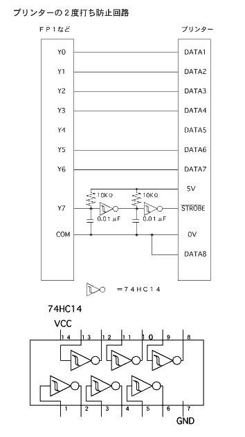
When I print using F147 (printout instruction), sometimes I end up with two printouts.
With the FP Series, it is possible to directly connect to the Centronics port on the printer. Although rare, some printers (particularly compact models) are not equipped with an anti-chatter circuit (Schmitt trigger). In such cases, connect an external circuit like the one shown on the following page to prevent double printouts.
Is it possible to use PLC Link while carrying out general-purpose communications (FPG-COM4)?
It is possible by using RS485 1channel and RS232C 1channel type communication cassette(FPG-COM4). Use CH2 for general-purpose communication and use CH1 for PLC Link. (In this case the limit on number of stations is 5 and the transfer distance becomes 100 m (total extension).) The following is a configuration diagram and setting example.
*Configuration diagram
- Station No. 1 setting
- Station No.2 setting
- Station No.5 setting

The error is not cleared even though clicking "Error clear" in the status screen.
If the error is cleared while the cause of the error has not been removed when the mode switch is set to RUN, the error will re-occur if the program is executed immediately after clearing the error. At this time the error is momentarily cleared, but the error LED continues to illuminate (flashed depending on the model), so it appears that the error has not been cleared.
In such a case, please perform the error clear in either REMOTE mode or PROG mode.
What is the allocation when using a remote I/O?
The allocation of the FP0 I/O link unit on the FP0 side differs depending on the expansion position. The variations are shown below.
*configuration
- When the first FP0 expansion unit is an I/O link unit:
- When second and third FP0 expansion units are I/O link units:
Is it necessary to designate separate station numbers for the MEWTOCOL stations when two CCU ports are used or when multiple CCUs are being used simultaneously?
The MEWTOCOL station numbers when using CCUs can be any number as long as they are in the range between 1 and 64. The same station number can even be used at the same time.
Is there an 8-bit-only transmission instruction?
There are no 8-bit transmission instructions.
Please use the F6 (digit transfer) instruction.
Example 1)
|---||---[ F6(DGT), HFF, H10 , WY18 ]
Explanation: HFF is transferred to Y180 to Y187.
|---||---[ F6(DGT), HFF, H10 , WY18 ]
Explanation: HFF is transferred to Y180 to Y187.
Example 2)
|---||---[ F6(DGT), HFF, H210 , WY18 ]
Explanation: HFF is transferred to Y188 to Y18F.
|---||---[ F6(DGT), HFF, H210 , WY18 ]
Explanation: HFF is transferred to Y188 to Y18F.
Can Data Register (DT) be used for a timer instruction setting?

Data Register (DT) can only be used in the setting for the two models, FP2SH and FP10SH. Although DT cannot be used in other models, timer/counter set value area (SV) can be used. Please use SV in place of DT.

If a contact identical to the MC instruction trigger (execution condition) begins from the mother line inside MC-MCE and a DF instruction exists immediately to the right, that contact won't be able to be differentiated even if the trigger (execution condition) turns on.
The DF instruction detects a rise when the previous OFF execution result is stored and the current execution result is ON. (The opposite applies for DF/.) In this program, although the DF instruction inside MC-MCE does not execute when the MC instruction execution conditions are first established after running, since there is no ON/OFF information from the previous execution, R100 does not turn ON because the rise cannot be detected.
Also, even when there are two or more subsequent MC instruction executions, if RO was on during the last scan when the previous MC instruction was executed, R100 will not turn on because the rise cannot be detected.
However, for only the FP2, FP2SH and FP10SH, detection will always occur when the checkmark in the item below is removed in the system register settings.
Is a battery required when performing ROM operation?
It is possible to operate even without using a battery, but the DT contents, on/off status of R and counter elapsed value that are all designated in the holding area will become indefinite when the power turns on. To preserve the status of these items after the power is turned off please use a battery.
When output COMMONs are together is it possible to connect voltages of differing loads?
It is possible by connecting the minus terminals of each power supply together in case of NPN output type.
Although the system register was set, the setting is not valid. What is wrong?
The settings will be valid from the first time you switch to RUN mode.
In the ROM used for ROM operation, is anything else contained besides the program?
Depending on the content of the system register, password, and product type, items such as DT and FL are contained in the memory aside from the program.
Is there PLC type for writing the contents of DT and FL to ROM?
This is possible with the FP2, FP2SH, and FP10SH.
As with a program, when using this function the ROM content is transferred to RAM (DT and FL area) when RUN mode is first entered after the power is turned on.
A manual alternate circuit is run, but on and off is not stable.
Chattering caused by the input (X0) is the cause.
The faster the CPU the more likely the effect of chattering. Chattering can be absorbed by using a timer instruction as shown below.![]()
The faster the CPU the more likely the effect of chattering. Chattering can be absorbed by using a timer instruction as shown below.
Are there any program examples for CRC for communications with a temperature controller?
Download the following the sample programs from our software page:
ÃÂâÃÂ?ÃÂ?FP? - KT Series Temperature Controller current temperature (PV value) reading (RTU mode)ÃÂâÃÂ?ÃÂÃÂ
ÃÂâÃÂ?ÃÂ?FP? - KT Series Temperature Controller set temperature (SV) writing (RTU mode)ÃÂâÃÂ?ÃÂÃÂ
How do I get the Chinese manuals for FP0 and FPWIN GR?
Unfortunately, the Chinese manuals for FP0 and FPWIN GR are not available in Japan. They may be available in Shanghai. You can check the Panasonic China website.
The English manuals are available in PDF format.
When I use F147 (printout instruction), the data is sometimes printed out twice. How do I prevent this?
FP series can be directly connected to the Centronics interface of a printer.
When connecting the unit to a general printer, there is no possibility of double printouts. However, some printers (compact type in particular) donÃÂâÃÂ?ÃÂ?t have a Schmitt circuit (chattering prevention circuit). In such cases, you can avoid double printouts by installing an external circuit, as shown below.
Although I used colored text for comments, they are printed in black and white even by a color printer. Are any settings required?
FPWIN GR Ver. 2.3 and later support color printing. If you are using an older version of FPWIN GR, download the difference file for upgrade from the following URL and install it.
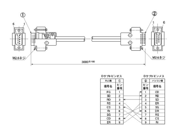
How do I connect the FP2 SDU to the serial port (9-pin type) of a DOS-V computer? The manual only describes the connection with a 25-pin type.
Use the AFB85853 connection cable. Refer to the following wiring diagram:
I need to move a tool in an S-shape by controlling two axes using FPG-C32T and FP0-E32T. How do I program them? I donÃÂâÃÂ?ÃÂ?t know how to program well.
Use F176 circular interpolation pulse output instruction to easily program the S-shaped positioning control. Please refer to FP Series Programming Manual.
Recent notebook computers donÃÂâÃÂ?ÃÂ?t have serial ports, but have USB ports only. How do I connect PLCs, such as FP0, FP1, and FP10SH to edit the programs?
You can use a commercially available RS232C-USB conversion cable.
I installed PCWAY Ver. 2.4 in Windows XP. However, the key unit for the printer port cannot be recognized. What should I do?
It is possible that the key unit control driver cannot be recognized on Windows XP. In such cases, you need to upgrade the driver. The difference file for the key unit driver Ver. 4.96 shared by PCWAY and COMMX is available. The file is called keyunit_spv496.zip.
How are I/O points allocated to expansion units added on the left side? If they are also added on the right side, will the I/O numbers change?
The I/O allocations of the left-side expansion units are as follows:
1st unit: X100 to X11F, Y100 to Y11F
2nd unit: X180 to X19F, Y180 to Y19F
3rd unit: X260 to X27F, Y260 to Y27F
4th unit: X340 to X35F, Y340 to Y35F
The I/O allocation numbers are fixed regardless of presence or absence of the right-side expansion units.
I need to expand the file register (FL) and use the comment memory. Which hardware is required?
IC card board (AFP6209A) and S-RAM card (AIC31000) are required. The IC card board has a 512-KB built-in memory for storing comments. When the IC card DOS size to 512 KB, the rest (512 KB) can be used as an expansion area.
AIC31000 is BN-01MHSRC made by Matsushita Battery industrial Co.,Ltd.
Is there a FP10SH hardware manual?
Visit our documents page to download the manual.
How do I connect the power line of FP0?
The power line connector is a Molex white connector. Use the connector with a cable (1 m) that comes with the unit for connection. Brown: +, Blue: -, Green: FG
Is it possible to set the internal relays of FP1-C14 to the data hold type?
Relays from R100 to R15F are set to the data hold type by default. If you need to set all relays to the data hold type, change the starting word number of the internal relay data hold area to ÃÂâÃÂ?ÃÂ?0ÃÂâÃÂ?ÃÂÃÂ, and write it in "PLC Configuration". The memory of this PLC is backed up by a built-in large-capacity capacitor for 10 days. Note that if the power failure continues for more than 10 days, the data cannot be held.
When using X0 to X4 as a high-speed counter, whatÃÂâÃÂ?ÃÂ?s the maximum counting frequency? And how do I set it? (I wonÃÂâÃÂ?ÃÂ?t use the pulse output function.)
If you donÃÂâÃÂ?ÃÂ?t use the pulse output function, limit the total of the counting frequencies inputted to the counter channels within 10 kHz. You donÃÂâÃÂ?ÃÂ?t have to preset the frequency. If the total exceeds 10 kHz, correct counting will be impossible.
How do I read and write data memory of FP0 in a batch?
Use "Data Editor" included in FPWIN GR. To activate it, go to Windows Start > All Programs > Panasonic MEW Control > FPWIN GR2, and click on "Data Editor". Select "Edit Data Register" and execute uploading from the PLC. With these procedures, you can read, save, and write data in any area you like.
I asked a trading company to estimate AFC13012 and AFC22342C, and the numbers in its reply included ÃÂâÃÂ?ÃÂ?-FÃÂâÃÂ?ÃÂÃÂ. WhatÃÂâÃÂ?ÃÂ?s the difference?
Previously, the part numbers were classified by the presence/absence of the CE marking. At present, all products have the CE marking. Therefore, all part numbers have ÃÂâÃÂ?ÃÂ?-FÃÂâÃÂ?ÃÂÃÂ. Please rest assured that there is no difference in the performance.
X and Y can be directly entered by using the X key and Y key on the keyboard. Can I enter WX and WY in the same manner?
You can enter WX and WY using the U and I keys respectively. For details, refer to the Operand Allocated Key List in "Shortcut keys for Operands" of Help.
Since FP0-T32CT had been powered off for a long time, the data in the data registers was invalidated.
The necessary tool is not locally available. How do I obtain a tool that has the same functions as "Data Editor"?
Download the trial version of FPWIN GR from the software section of our website. Since there are no limitations with "Data Editor" included in the trial version, you can use all of its features as you would with the full version.
Since the program space becomes insufficient, I need to change the CPU unit. If I change FP2 to FP2SH, can the other units be used as they are?
Their memory units and ROMs are not compatible. But the other units can be used as they are. The programs are also compatible.
When rewriting the program, all data in the data area are reset to zero. Therefore, I tried to hold the data by using "Hold PLC Device Value" function of GT10. However, the data still became zero. How can I successfully hold the data?
First of all, "Hold PLC Device Value" function of GT10 is intended to hold data in case of a power failure, and cannot be used for holding the data area. If you need to save the data in a specific area, use "Data Editor", which is software supplied with FPWIN GR. Go to Start of Windows > All Programs > Panasonic MEW Control > FPWIN GR2, and activate "Data Editor". With this software, you can easily read, save, and write any data area of PLC, including an IC card.
The computer I purchased has only USB ports. Since I need to program the sequencer using FPWIN GR, is it possible to connect it via a USB port?
Communications are possible by using a commercially available USB-RS232C conversion cable or adapter.
Make sure to check the new COM port number that will be assigned by the computer for the USB when the USB-RS232C conversion device is registered.
You can check the number in Windows 98/Me by going to Start > Control Panel > System > Device Manager > Ports.
For Windows XP, go to Start > Control Panel > System > Hardware > Device Manager > Ports.
Then, if the assigned port number is COM4 for example, activate FPWIN GR, go to Options in the menu bar > Option > Communication Settings, and change the port number to COM4 to enable the communications.
How do I adjust the response time of communications between FP? and a computer via RS485?
With the SYS1 instruction, you can set the response time of the COM port within the range from 0 to 999 ?sec.
Can an expansion I/O unit be connected to FP0 SL1?
Up to three units can be connected.
The RUN and ERROR LEDs of FP3 are lit.
There is a self-diagnosis error. Connect a programming tool, such as FPWIN GR, Status Display to check the details of the error, and take corrective actions.
How do I write programs in the FP-M master memory (EEP-ROM)?
Power off the unit, install the master memory in the FP-M unit, and set the memory selector switch to EEP-ROM.
Then, make sure to power on the unit in PROG mode. (If you power on in RUN mode, the program will be automatically written to RAM from ROM, overwriting the program you wrote.)
Then, execute the RAM -> ROM transfer(ROM&RAM Survice) using a programming tool, such as FPWIN GR.
IÃÂâÃÂ?ÃÂ?m using four interruption input points of the FP2 high-speed counter unit. How does the unit operate when multiple interruption instructions are executed simultaneously?
The unit executes instructions one at a time in ascending order of interruption program number (INT No.). Therefore, they are not executed simultaneously.
Since an electric leakage is caused, IÃÂâÃÂ?ÃÂ?m planning to measure the insulation resistance between the FP0 power supply and FG using a 500-V megger for investigation purposes. Will there be any problems?
There will be problems. Since there are varistors (39 V) between the power supply (-) and FG, and between the power supply (+) and FG, they will break.
For the same reason, if the voltage between the power line and the ground is excessively high, the varistors may be short-circuited when FG is grounded.
If CH0 and CH2 of FP? are programmed for positioning so that only one of the channels outputs pulses at a time, is it possible to achieve a 100kHz output frequency?
Yes, a 100kHz output frequency can be achieved if either CH0 or CH2 outputs pulses at the same time. If they simultaneously output pulses, the frequency is 60kHz at the maximum.
Can the cable supplied with FPWIN GR (AFC8503) be used for FP1?
No, it canÃÂâÃÂ?ÃÂ?t be used. You need a dedicated cable (AFP15205 or AFP1523), the conversion adapter (AFP8550), and a commercially available RS232C straight cable.
I need to have the FP2 positioning unit multifunction type perform home position return, but there are not near-home position switches. How do I set it if there are only limit switches on both ends and a home position switch?
There are three ways.
(1) Set bit 5 of the control code to 1 so that the near-home position logic will be enabled without current passing through. In this setting, the object moves at the startup speed and stops at its home position. However, if the object is in a position beyond the home position, it moves to the limit switch, stops, and then an error occurs.
(2) This method uses the difference between positions where the input signal of the home position dog is turned ON and OFF. Connect the home position switch in parallel with the home position input and the near-home position input first. Set bit 4 of the control code to 0 (home position input logic: Enabled during no current application), and bit 5 to 0 (near-home position input logic: Enabled during current application) so that the object stops when the home position dog turns off. In this setting, the home-position search function can be used.
(3) Connect the home position switch to the near-home position input, and connect nothing to the home position input. Set bit 4 of the control code to 0 (home position input logic: Enabled during a no-current application), and bit 5 to 0 (near-home position input logic: Enabled during current application) so that the object starts to decelerate when the home position switch is turned on, and stops when the speed reaches the startup speed. There is no sensor in the stop position; however, the object can stop at the same position every time because there are no variations in the deceleration time. The home-position search function can also be used with this setting.
Is it possible to read a program from an FP0 unit in use and write it in another FP0 unit by only using FPWIN GR and the dedicated cable? Is there any other way?
If you have FPWIN GR and an AFC8503 cable, the program can be read from FP0. (Note that if a password is set, the program cannot be read without entering the password.) The read program can be written in another FP0 unit as is. Of course, it can also be saved on a hard disk.
The other way is to use FP Memory Loader (part No. AFP8670, or AFP8671). Connect it to the TOOL port, set it to download, and then press the button to read the program. The read program is saved in F-ROM of the FP Memory Loader. Therefore, it will never be erased. Connect it to the TOOL port of another PLC, set it to upload, and then press the button to complete writing. Since reading/writing with this tool does not require a PC, it is suitable for on-site operation.
WhatÃÂâÃÂ?ÃÂ?s the difference between FL (file register) and DT (data register)?
Their purposes of use are the same, but the storage areas are different. The file registers(FL) are in the program area, and the part that is not used for programs can be allocated as data memory(DT). Therefore, the FL area changes depending on the program area size settings. On the other hand, the data registers use the operation memory area.
When the I/O points of FP2-XY64D2 are allocated, will the output points be Y30 to Y4F if the input points are X10 to X2F? Can Y numbers be allocated first instead?
For I/O mixed units, the input numbers are allocated first, and then the output numbers are allocated without exception. Therefore, you canÃÂâÃÂ?ÃÂ?t set the Y numbers first.
The auto-tuning progress indication repeats 0->1->0->1, and the proportional gain or derivative time cannot be set. WhatÃÂâÃÂ?ÃÂ?s the problem? Since the regular temperature control is functioning correctly, I believe that there are no problems with the connection.
It is possible that the operation data area value used in the parameter table has been rewritten by another program. Check if the 31-word data registers are used by another program. The F355 (PID) instruction can be used in only one section of the entire program. Do not include it in more than one section. Otherwise, correct control will be impossible. If there are multiple execution conditions, use the OR instruction or others to activate the F355 instruction.
Are there internal relays that can check if each process of the FP0 step ladder is executed?
The bits of special registers from DT9060 to DT9067 are turned on during the operation of each process. Therefore, for example, if you execute [F0, DT9060, WR10] to replace the bit information of each process operation in DT9060 with operations of the internal relays (R100 onwards), you can check execution of each process based on the internal relay operations.
FP0-T32CT has a built-in rechageable battery. Does it have a battery exhaustion alarm function?
No, it doesnÃÂâÃÂ?ÃÂ?t have a battery exhaustion alarm function. The rechageable battery is only for backup purposes. We recommend that you write data that must not be erased in the F-ROM area using the P13 instruction.
Which is better to create a relay sequence program for FP0, FPWIN GR or FPWIN PRO?
We recommend FPWIN GR to create relay sequence programs. It is compatible with the earlier software NPST-GR.
FPWIN PRO is program editing tool software based on the IEC61131 European standard. It supports ST, a PASCAL like language, SFC, a language that can be structured, and other high-level languages. Therefore, this software is suitable for reusing programs by structuring them. However, it cannot read programs from FP0, and the source files must be managed. So, use FPWIN GR unless you need these FPWIN PRO functions. Note that the FPWIN GR and FPWIN PRO programs are not compatible.
How do I connect GT30 to FP??
Connect the COM port of GT30 and the TOOL port of FP? using an AIGT8192 cable. Use the TOOL port of GT30 for screen creation. The ÃÂâÃÂ?ÃÂ?ThroughÃÂâÃÂ?ÃÂàfunction allows you to operate FP? programming and monitor communications through the TOOL port of GT30.
When I change the device by going to Edit > Change Device, the comments sometimes remain and sometimes donÃÂâÃÂ?ÃÂ?t depending on the combination of the change method [Interchange (Source<==>Destination) or Overwrite (Source==>Destination)] and whether or not the I/O comments should be changed. How do the devices change depending on the combination?
(1) Device: Interchange (Source<==>Destination) I/O comments: Change
The devices interchange their positions on the ladder, but their comments remain at the original position on the ladder. So, each combination of device and comment also changes.
(2) Device: Interchange (Source<==>Destination) I/O comments: Not change
The devices interchange their positions on the ladder together with their comments. So, each combination of device and comment does not change.
The devices interchange their positions on the ladder together with their comments. So, each combination of device and comment does not change.
(3) Device: Overwrite (Source==>Destination) I/O comments: Change
The source device will be overwritten with the target device, and the source deviceÃÂâÃÂ?ÃÂ?s comment will be attached to the target device. The source deviceÃÂâÃÂ?ÃÂ?s comment will be deleted.
The source device will be overwritten with the target device, and the source deviceÃÂâÃÂ?ÃÂ?s comment will be attached to the target device. The source deviceÃÂâÃÂ?ÃÂ?s comment will be deleted.
(4) Device: Overwrite (Source==>destination) I/O comments: Not change
The source device will be overwritten with the target device together with its comment. The source deviceÃÂâÃÂ?ÃÂ?s comment will also remain.
The source device will be overwritten with the target device together with its comment. The source deviceÃÂâÃÂ?ÃÂ?s comment will also remain.
(1) and (2): If the specified ranges of the source and target devices are overlapped, the interchange is impossible.
(3) and (4): Even if the specified ranges of the source and target devices are overlapped, the overwrite operation will be executed (although a warning message will appear).
(3) and (4): Even if the specified ranges of the source and target devices are overlapped, the overwrite operation will be executed (although a warning message will appear).
For example, when you need the source deviceÃÂâÃÂ?ÃÂ?s comment to remain and to be attached to the target device, you need to execute overwrite method (4) above, and then copy and paste the source deviceÃÂâÃÂ?ÃÂ?s comment to the target device using the batch I/O editing function.
How long is the life of the backup battery for FP1?
For the standard type: 53,000 hours For C type (with the RS232C port): 27,000 hours
Does the FP1-C40 indicate anything when the battery is exhausted?
The ERROR indication LED is turned on. The special internal relays R9005 and R9006 are also turned on. We recommend that you output the signal to a lamp or a buzzer using these relays. Note that the ERROR indication LED does not turn on if you disable Alarm battery error at No.4 in PLC Configuration.
Can a programmable console be used for FP10SH?
Programmer II can be conditionally used. Use AFP6523 cable for connection.
Generally, the 16 output points are required to display values using a four-digit digital display (BCD type). But is there any way to use only eight output points?
It is available by using the dynamic output method. With this method, displaying four-digit values requires only eight output points, and displaying eight-digit values requires only 12 output points.
Refer to the attached sample programs.
Can the F-ROM writing instruction (P13) be used for the standard type?
Yes, it can be used.
How do I establish both a PLC link and general-purpose communications using FP??
Use the newly released communication cassette AFPG806. This cassette allows a single unit to support RS232C(general-purpose communications) and RS485(PLC link) .
If a communication error occurs during W-link communications, what will happen to the link relay or link data? If a communication error occurs during F-link, what will happen to the output?
In the case of a communication error during W-link, both the link relay and link data will hold their last status. In the case of a communication error during F-link, the slave station output will generally be turned off. However, if you turn on DIP switch No. 3, the last status can be held.
When replacing FP1-C40 and an expansion unit (eight output points) with FP0, can I use the FP1 programs for FP0 as they are?
You need to convert the I/O addresses.
In addition, if you use instructions dedicated to FP1, you need to change the programs. (Change F162 and F163 to F166 and F167. Add required programs to F164 and F165.)
FPWIN has a function for the batch conversion of I/O addresses.
Can the FP2 multi-wire link unit be used as either a master or slave station? (I need functions equivalent to those of the FP3 slave unit.)
Use as a slave station is impossible. You can use the FP3 slave unit for FP2multi-wire link unit(MEWNET-F mode).
Can S-LINK be connected to an FP3 slave unit?
No, it canÃÂâÃÂ?ÃÂ?t.
GT30 made a general-purpose serial communication setup is connected to the COM port of FP2. However, they donÃÂâÃÂ?ÃÂ?t communicate. There are no problems in either the cable connection or electric continuity.
If the target PLC of GT30 is set to ÃÂâÃÂ?ÃÂ?general-purpose serial communicationÃÂâÃÂ?ÃÂÃÂ,communications with FP2 are impossible. In this case, go to File > Utility > Convert PLC Model, and select Matsushita MEWNET-FP Series.
Do I need to replace the battery to back up the user programs or data of FP0 C32T?
With regard to this model, all user programs, system registers, and data set to the hold type are saved in F-ROM. If you need to hold the non-hold type data, write it to F-ROM using the P13 (write) instruction and read it from F-ROM using the F12 (read) instruction.
FP0 T32T has a built-in Rechageable battery. This type can hold data in case of a power failure without using the P13 and F12 instructions.
An error occurred when I tried to write data to an IC card (F-ROM) inserted in FP10SH using a program. Why?
Since F-ROM is a read-only memory card, data writing by a program is impossible. Data writing is only possible with "Edit Data Resister".
If you need to write data by using a program, use the S-RAM IC memory card (part No.: AIC31000).
Which cable should I use to connect an NEC PC98 series computer to FP10SH?
Since the serial port of your PC is the 25-pin D-Sub type, use AFB85813.
FP1: PROG and ERROR indicators lit up. Has the battery been depleted?
If the mode switch returns to PROG mode even when you turn it to RUN mode, it is possible that the user program has already crashed due to battery depletion.
Purchase an AFP1801 battery , and replace the depleted battery with the new one. Then set the user program again.
IÃÂâÃÂ?ÃÂ?m using ch1 to ch6 of the FP2 A/D unit for current input. When increasing the current input to channels other than, for example, ch1, the reading of ch1 also increases accordingly. How do I prevent this?
The common pins of the input channels of the FP2 A/D unit are connected internally. Therefore, they may be affected by a change in the other channel.
With this unit, the voltage input is more stable than the current input. If the converted values with the current input fluctuate, we recommend that you adopt the voltage input.
Change the connection as shown in the attached file to adopt the voltage input without changing the settings or programs. (Digital conversion of the input range from 1 to 5 V)
Tell me the data hold area of FP0.
C10/C14/C15: Four counters from C140 to C143; 32 internal relays from R610-R62F; and eight words of data registers from DT1652 to DT1659.
C32/SL1: 16 counters from C128 to C143; 128 internal relays from R550 to R62F; and 32 words of data registers from DT6112 to DT6143.
T32: Since it has a built-in secondary battery, all points can be set to the data hold area.
I need to use a flat cable for connecting the FP? 64-point I/O units. Which connectors should I order?
Purchase AFP2802 (a set of two connectors with a strain relief).
What precautions must be taken for using the data backup battery for FP??
The backup battery does not come with the FP? unit. If you need it, purchase it separately. The part number is AFPG804.This battery is used for holding data in the memory in the event of a power failure, and operating the calendar timer. The battery life is approx. 220 days under no energization. Replace it approx. once a year.
Connect a new battery within 2 minutes after removal of the old one for replacement.
WhatÃÂâÃÂ?ÃÂ?s the part number for ordering the CR2450 battery for backing up PLCs?
The part number is AFC8801. It is for a battery for the FP2 CPU unit.
Seven PLC units are connected in the MEWNET-H link system. I set the system so that when a change is made to the file register (FL) of the first to the sixth units, the seventh PLC unit externally outputs the data of the changed FL. However, all are turned OFF. When I checked the error history by using MEWNET-H setting software, three out of the seven units showed an ÃÂâÃÂ?ÃÂ?undefined errorÃÂâÃÂ?ÃÂÃÂ. Why does this error occur? When this error occurs, does it have any other effects?
The undefined error occurs in the case of a momentary power interruption, contact failure of the coaxial connector, noise, and other problems (the cause cannot be identified). Even if this error occurs, it is ignored, and FL clearing or other operations will not be executed. We recommend that you check for differences between those conditions before and after the error occurred, such as changes in the coaxial cable processing or installation of a noise source near the units.
How do I hold data in the FP-e data register in case of a power failure?
FPWIN GR has an FP-e system register setting section where the data hold area of the data register (DT) can be set. However, this setting section is only for the calendar timer type (AFPE224305 and AFPE214325).
Therefore, never set the data hold area for the other types. Otherwise, every time the unit is powered on, out-of-control values may be recorded in the data register, causing unexpected operations. Nevertheless, if you must hold data in the data register of the other types, follow the following procedures:
(1) Write a program that will write the required data in the built-in F-ROM using the P13 instruction before power-off, automatically execute the F12 instruction using the initial pulse relay at the time of power-on, and read the data into the original data register.
(2) For automatic detection of the power-off state, use an AC power type mechanical relay, and make a circuit and a program so that the P13 instruction will be executed upon detection of the moment when the B-contact of the relay is opened.
(2) For automatic detection of the power-off state, use an AC power type mechanical relay, and make a circuit and a program so that the P13 instruction will be executed upon detection of the moment when the B-contact of the relay is opened.
Avoid writing a program that executes the P13 instruction at every scan using an always-on relay because the F-ROM writing is limited to approx. 100,000 operations.
When connecting GT30 touch panel to the TOOL port of FP10SH, how do I achieve a communication speed of 115.2 kbps? The DIP switch for setting the communication speed of the CPU unit can only switch between 19,200 bps and 9,600 bps.
Set the communication speed setting DIP switch of the FP10SH CPU unit to 19,200 bps (turn OFF No. 1). Then open FPWIN GR programming software, go to Option > PLC Configuration > COM Port > No. 414 TOOL Port Baudrate, and select 115,200 bps. Upload this setting to FP10SH to complete.
When connecting GT30 to FP0, error 61 is indicated. Why?
The error occurs when you specify a device that cannot be used by FP0 (e.g. contacts and data registers) as a screen data part of GT30. Check the device setting details of the registered parts and change them to devices that can be used by FP0.
GT30: Can I switch screens by using both the function switch and programmable controller?
You can switch the screens using the function switch by directly designating a screen number regardless of the controller status. You can also switch the screens from the controller by writing the screen number data in DT0. However, if you use both methods, there will be a difference between the screen switching data in DT0 and the currently displayed screen data in DT2, and screen switching by the controller may be impossible. In such cases, set the screen switching data in DT0, and then set and reset the forced screen switching flag (internal relay RE).
What is the Molex part number of the AFP0805 optional Molex connector crimping tool for FP0?
Molex 57189-5000
APL1634 has been discontinued. What is the substitute product?
Purchase the FP0 power supply unit AFP0634. Since it is a DIN-rail mount type, prepare a DIN rail. If you donÃÂâÃÂ?ÃÂ?t have a DIN rail, we also have an optional dedicated mounting plate (AFP0803).
I upgraded FPWIN GR to Ver. 2 successfully with the upgrade version, but Ver. 1.1 still remains. May I uninstall it since it is no longer necessary?
Yes, you can uninstall it. But make sure to leave the shared files installed during the uninstallation operation.
I tried to upgrade FPWIN GR for FP-e. But I couldnÃÂâÃÂ?ÃÂ?t uninstall the previous version from some PCs. How do I solve this?
The CD-ROM of FPWIN GR Ver. 2 includes a file named ÃÂâÃÂ?ÃÂ?setup uninstallÃÂâÃÂ?ÃÂÃÂ. Go to Start, Run, type this file name, and press OK to uninstall the previous version.
Regarding FP-e, I need to prevent the current screen from jumping to another even when the mode switch is pressed. For example, when I want to use only normal screen 1, what setting is required?
Execute the screen display switching instruction (F181) using R9010 always-ON relay in order to keep the designated screen always displayed.
IÃÂâÃÂ?ÃÂ?m using a combination of FP? (FPG-C32T2) and the communication cassette (FPG-COM1) for the FS232C transfer. However, the hardware flow control of RS-CS doesnÃÂâÃÂ?ÃÂ?t work well. Even when I directly monitor the terminals, no changes were found. I must get the FP? flow control working so that I can send large volumes of data. How do I stop the transmission request (RS: LOW)?
Use the SYS1 instruction, which allows you to control the transmission request, for RS control of the communication cassette (FPG-COM1).
RTS1 disables communications, and RTS0 enables communications. For details, refer to the Programming Manual.
Which instruction should I use to convert BCD data to decimal numbers for comparison?
Use the F81 instruction for conversion of four-digit BCD into decimal numbers (16 bits). Use the F83 instruction for conversion of eight-digit BCD into decimals (32 bits).
The comparison instructions apply to comparisons between decimal numbers, Use the F60 instruction for 16-bit decimal numbers, and F61 for 32-bit decimal numbers. In addition, ladder comparison instructions, such as ÃÂâÃÂ?ÃÂ?ST>ÃÂâÃÂ?ÃÂàand ÃÂâÃÂ?ÃÂ?AN<ÃÂâÃÂ?ÃÂÃÂ, which can be used as though it were contacts, are also available.
How do I connect FP3 and FPWIN GR?
Purchase the conversion adapter (AFP8550), the cable (AFP5520 or AFP5523), and a commercially available straight cable (9-pin female - 25-pin male for a DOS/V machine).
Do you have a resistance temperature detector unit for FP2?
You can use the FP2 analog input unit as an RTD unit by adjusting the input range. The thermocouple/RTD input units of FP3 and FP10SH are separated from the input units. However, the input units of FP2 and FP2SH can also serve the thermocouple/RTD input units.
IÃÂâÃÂ?ÃÂ?m now programming FP2, but I canÃÂâÃÂ?ÃÂ?t enter CT100. Why?
The system register counter number of FP2 starts from 1000 by default. Set the counter starting address to 100 by editing the system register(PLC configuration) in order to enter CT100.
Are 2-ch serial communications possible for FP0 without using the TOOL port?
Not available with FP0. For FP?, we have FPG-COM2, a 2-ch communication cassette (AFPG802). Therefore, we recommend that you use FP?.
When converting programs for FP2 to FP2SH, CT1000 was changed to TM1000. How do I restore it?
The counter number of FP2SH starts from 3000 by default. Set the counter starting address to 1000 by editing the system register(PLC configuration).
I purchased FPWIN GR Ver. 2 (Part No. AFPS10122) for FP1-C24. However, the supplied cable cannot be used. How do I solve this?
The cable supplied with AFPS10122 is for FP-X/FP0/FP?/FP-M/FP-C/FP2/FP2SH/FP-e. For FP1, you need an AFP1523 cable (3 m) or AFP15205 cable (50 cm), AFP8550 adapter, and a commercially available RS232C straight cable.
Can FP0 use FIFO-related instructions (from F115 to F117)?
No. FP-X,FP?, FP2, FP2SH, FP3, or FP10SH can use them.
The FP3 I/O units (e.g. AFP33024-F, AFP33484-F) have 20P type sockets. I need to order the wire-press connector separately. What is the part number?
Every unit requires two AXW1204A housings, two AXW62001A covers, and eight AXW7221 contactors.
GT30 cannot communicate with a notebook PC. (FP2 can communicate with it. Both FP2 and GT30 can communicate with a desktop PC.)
Set the Transmit Buffer slider to the lowest position in the advanced settings for the COM port of your PC. If this does not solve the problem, please purchase a commercially available USB-RS232C converter and connect it to the USB port.
How do I expand the data register area of FP2?
Add expansion memory FP2-EM2, EM3, or EM6 to the CPU unit. Adjust the sequence program area size in the Memory Allocation tab of the PLC Configuration setting window of FPWIN GR or other tool software in order to increase the file register FL capacity that can be used in the same manner as the data register.
I need to connect the AFP2430 FP2 positioning unit to Y companyÃÂâÃÂ?ÃÂ?s SGDM-01AD motor driver, but the deviation counter clear signal input CLS is the line driver input. Since the output of the FP2 positioning unit is an open collector, how do I connect them?
Include a 2-k? resistor in series with the open collector terminal (e.g. A6 terminal) to drive the CLS input by a 24 V DC power supply.
What hardware is required to connect FP3 to my PC for program maintenance? Also, what hardware is required to connect the data processing unit?
The tool software is FPWIN GR (Part No.: AFPS10122). For connection, prepare an AFP15205 cable, AFP8550 adapter, and a commercially available RS232C straight cable. For the Data Processing unit, prepare DP-TERM software (AFP866518) and an AFB85853 cable.
Since I forgot my password, I forcibly released the protection. Then the PC froze. How do I solve this?
When the forced password release is executed, the completion can take a maximum of one hour to complete. During this process, FPWIN GR operation is impossible. However, this does not mean that the PC will freeze. Please activate another application from the Start menu or the task bar, and you will be able to see that it can operate.
When indicating a constant into the input "S" portion of instruction words (F1_DMV etc.), is it satisfactory even if it carries out a direct entry to "VAR"?
For example, Hex is H1125 and DEC is K0.
Moreover, how should be carried out to write a Hex value to the Initial portion of variable registration?
It will become a compile error if H1125 is described .
When treating a constant, it uses carrying out constant variable "VAR_CONSTANT" creation.
In the case of a hexadecimal number, a data type is set as WORD, and the input of an initial value attaches 16# to a numerical head.
For example, H1125 inputs 16#1125.

Although the program of FPsigma is created by FPWINPRO, please let me know about a setup of a global variable.
1.If a class is made into VAR_GLOBAL_RETAIN, can DT of non-hold area be held (since there is too little hold area at 6 words)?
2.It will become a compile error if a Global variable is specified and registered into D-Word types (data relation for motor control, acceleration, etc.). Why is it?
3.Although it seems that there is also quite little area of R when assigning an internal relay to switches and lamps, such as a touch panel, and registering an internal relay into a global variable, is there any method of expanding?
1.DT does not become the class of a global variable as for VAR_GLOBAL_RETAIN in hold area. In order to make it hold area, please build in the battery of FPsigma first. (Battery ordered-parts number:AFPG804) Next, please change the start address of data register hold area in the setting portion of hold/non-hold of the system register. It is set as 0 to make it all-points holdding. Moreover, since you can change in the address range of a compile option as Extras -> Options of a menu bar to change the range of user area and a system area, please set up arbitrarily. In addition, in case a program is rewritten, in order not to initialize the value of hold area, please be sure to put a check mark into "Retain variables in the user area notinitialized" in the code generation of a compile option.
2.For setting a DWORD type as a global variable,"DDT" is used in case FP address is specified.
Class: VAR_GLOBAL_RETAIN
Identifier: ICHI01
FP Address: DDT0
IEC Address: %MD5.0
Type: DWORD
Initial: 0
In addition, it is better to make a data type into "DINT" in the case of the data for motor control. (DWORD becomes the treatment of a hexadecimal number and DINT becomes the treatment of the integer of ÃÂ?ÃÂñ.)
Identifier: ICHI01
FP Address: DDT0
IEC Address: %MD5.0
Type: DWORD
Initial: 0
In addition, it is better to make a data type into "DINT" in the case of the data for motor control. (DWORD becomes the treatment of a hexadecimal number and DINT becomes the treatment of the integer of ÃÂ?ÃÂñ.)
3. Since you can change the range of user area of the internal relay R like DT. Please set up arbitrarily in the address range of a compile option as Extras of a menu bar -> Options.
Please teach me how to use the positioning start point of contact (TIM) for JOG positioning of Y?9 by FP2 positioning unit multifunctional type.
In JOG positioning control, JOG operation of JOG positioning control starts first by making the point of contact of Y?8 turn on, but if the timing input of an external input (terminal B5, B14) enters, from the time, positioning operation will be begun and will be stopped in the decided position. The point of contact of Y?9 is a point of contact for internal processings for shifting to positioning operation to arbitrary timing on a sequence program instead of this timing input.
An error occurs when the maximum number of editable lines of FPWIN GR is exceeded. How do I solve this?
The maximum number of editable lines is the maximum number of program lines that can be converted in Ladder Symbol View(LDS) editing mode. When this limit (33 lines) is exceeded, the error occurs.
Delete the excess lines. When programming in Ladder Symbol View(LDS) editing mode, frequently execute the program compiler.
Can I hold the data of all FP0 data registers?
It is impossible to automatically hold the data of all registers. C10/C14/C16 can hold eight words from DT1652 to DT1659, and C32/SL1 can hold 32 words from DT6112 to DT6143. It is possible to manually save all data registers to the F-ROM area by using the P13 instruction (F-ROM writing) and the F12 instruction (F-ROM reading). Don't execute it by using R9010 (always ON). Note that the F-ROM writing is limited to approx. 100,000 times for C14/C16 and 10,000 times for C32/SL1.
A transmission buffer error sometimes occurs during operation of FPWIN GR. Is there a remedy?
Go to Windows Start > Settings > Control Panel > System > Device Manager > Ports > COM1, and open Properties. Go to Port Settings > Advanced, and set the Transmit Buffer slider to the lowest position to solve the problem.
Although I replaced the battery, the mode switches to PROG with the ERROR lamp lit immediately after I switch the mode to RUN.
The program was deleted or crashed due to battery backup failure of the built-in RAM battery. Please enter the program again.
Can the FP Programmer II be connected to FP-e?
Basically, it is not supported although some functions can be used. Please use FPWIN GR Ver. 2.2 or more one of PC software instead.
I connected the COM port of FP2 CPU to the TOOL port of FP?, and connected a touch panel to the COM1 of CCU (computer communication unit). But they did not communicate. FPWIN is connected to the TOOL port of FP2 CPU. How do I solve this?
FP2 can use up to two ports(computer communication function) simultaneously. The TOOL port and COM1 of CCU cannot be used simultaneously. If you switch FPWIN connected to the TOOL port offline, communications with the touch panel is possible. This restriction doesnÃÂâÃÂ?ÃÂ?t apply to FP2SH.
Must a common power supply be used as the external power supply of the FP2 16-point NPN transistor output type and the power supply of the loads? Can Y0 and Y1 be used at different voltages?
There are no problems with the use of separate power supplies. If a common negative line is used, every load can use a different power supply.
Since I need to use the COM port of the CPU unit to which PCWAY has been connected for other equipment, I want to add an SDU and connect it to PCWAY. Will there be a problem?
PCWAY cannot operate with SDU. Connect your PC with PCWAY installed to CCU (computer communication unit) or connect it to the TOOL port of the CPU unit. Please note that the COM port of FP2 CPU and the COM2 port of CCU cannot be used simultaneously. Also avoid the simultaneous use of the COM1 port of CCU and the TOOL port of FP2 CPU. These restrictions donÃÂâÃÂ?ÃÂ?t apply to FP2SH CPU.
What accessories come with FP0?
The power cables and connectors (terminal block sockets/Molex sockets/ wire-press sockets) come with FP0. The quantities depend on the unit type.
How do I arrange the data in "Edit Data Register" into a single column?
Launch "Edit Data Register" and go to "Tool" in the menu bar and choose "Option". Set the number of columns to 1.
Can I connect SUNX two-wire proximity sensor GX-UF series to FP0?
Yes. You can connect the sensor because the OFF current of FP0 is 1 mA and the leakage current of GX-UF is 0.8 mA.
How do I use the calendar timer of FP0-T32CT?
You can easily set the calendar timer by using the time setting function of FPWIN GR.
In the state of on-line, please open a teime setting function(Tool > Set PLC Data & Time) and set up the date and time.
The calendar timer data is set to DT90053 (hours and minutes read only), DT90054 (minutes and seconds), DT90055 (day and hour), DT90056 (year and month), and DT90057 (day of week). DT 90054 to 90057 can be written by the F0 instruction, but they donÃÂâÃÂ?ÃÂ?t become effective until H8000 of DT90058 is written.
IÃÂâÃÂ?ÃÂ?m using NPST GR in the DOS window of Windows, but the window closes when I press Ctrl+Esc to switch online/offline. How do I solve this?
Open Properties of NPST GR. Click the Others tab and uncheck the box of Ctrl+Esc in the WINDOWS shortcut keys section.
In addition to AFP8550 and AFP5520, what is required for connection between FP3 and a personal computer (Windows)? Can this accessory combination also be used for any other PLC?
You need a commercially available straight cable (25 pins - 9 pins). AFP8550 can also be used for FP1, but a dedicated cable (AFP15205 or AFP1523) is required.
When setting remote I/O control of FP2SH, I set the slave unit 3 to 32E as a dummy to skip I/O numbers, but it didnÃÂâÃÂ?ÃÂ?t operate. How do I solve this?
For user allocation settings, change the remote I/O settings of the system registers(PLC Configuration) to ÃÂâÃÂ?ÃÂ?Start without waiting for slave station connectionsÃÂâÃÂ?ÃÂàin order to achieve normal operations.
Which tool is required for programming FP1? IÃÂâÃÂ?ÃÂ?m using a DOS/V machine.
Prepare the programming software (AFPS10122), conversion adapter AFP8550, dedicated cable (AFP15205 or AFP1523), and a commercially available straight cable for RS232C connection (25 pins - 9 pins).
When monitoring the conversion of a real number into an integer by the F330 instruction using FPWIN GR, the conversion data is displayed as ÃÂâÃÂ?ÃÂ?0.00000000000ÃÂâÃÂ?ÃÂÃÂ. Is this all right?
This is caused since the instruction handling real numbers cannot display integers. Please rest assured that this is not abnormal.
I need to import the PLC programs into NPST-GR, but Program Transfer <- -> PC in Program Manager is enabled. How do I solve this?
It is enabled because the PC is off line. Switch to online by pressing CTRL+ESC.
What will happen if the single frame command is executed during multiple frame processing by the multiple frame command of MEWTOCOL without aborting processing?
Procedural error E43 occurs, and communications will be reset.
Is there a difference between IX and IY?
There are no differences. They can be used in the same manner. Please note that when using index modification in units of 32 bits, designation of IX automatically sets the high 16 bits to IY.
How do I collect and monitor data in a batch with FPWIN GR?
Use "Edit Data Register" software packed with FPWIN GR. To activate it, go to Start of Windows > Programs > Panasonic MEW control > FPWIN GR2 >Edit Data Register .
FP1-C40C is suspended with the ERROR lamp lit. What are the possible causes?
If the cause is noise, power off and then on, and operation will be possible. If not, another possible cause is battery exhaustion. Since battery exhaustion may damage the program, write the saved program again after battery replacement.
Although FPWIN GR is connected, the message ÃÂâÃÂ?ÃÂ?Failed to connet with PLC.ÃÂâÃÂ?ÃÂàappears. IÃÂâÃÂ?ÃÂ?ve changed the OS to Windows 2000. The problem did not occur with the previous PC. The current PC is a DOS/V machine.
Recheck the RS232C port of the PC and its settings. Go to Control Panel > System > Port, and check that COM1 is enabled. Then, go to Properties of COM1 > Advanced, and set the transmission buffer to the minimum value. If there are any problems in communications even after the above procedures, please try connecting the USB-RS232C conversion cable to the USB port.
Regarding FP2, will there be any problems if the sequence program area size is set to the maximum, and FL (file register) is eliminated?
There are no problems unless the program uses FL. When the program is 2 K, the number of program steps is 1,534, and FL is 14,333 words, and you can change the user memory allocation to the program and FL in increments of 2 K words (2,048 words).
Which cables and tools are required for connection between FPWIN GR (DOS/V machines) and FP1?
Prepare AFP15205 (or AFP1523), AFP8550, and a commercially available modem connection cable for DOS/V.
Which I/O connector should I use for FP?? Which wire should be used for the connector?
Since the wire-press connector is supplied with FP? as standard, you donÃÂâÃÂ?ÃÂ?t need to purchase it separately. If you need a flat cable connector, use AXM110915 with a strain relief. The wire to be used is AWG #22 or #24.
Which cable should I use for connecting FP0 to FP Programmer II?
Use AFC8521 (Length: 1 m) or AFC8523 (Length: 3 m).
When FPWIN GR reads programs, the message ÃÂâÃÂ?ÃÂ?General memory not exist.Comments not uploaded.ÃÂâÃÂ?ÃÂàappears. Is this all right?
ItÃÂâÃÂ?ÃÂ?s all right. This message appears when the optional memory for comments is not embedded in FP2. If you need to write comments in the FP2 unit, purchase the optional memory for comments.
Can FPWIN GR read programs with comments prepared by NPST-GR?
The programs, including the comments, can be read.
Both FP0 and FP0 SL1 carry out general-purpose communications. Why can data be received only once?
Although data is transmitted every time the F144 instruction is executed, it cannot be received unless the receive buffer is cleared. To solve this, execute the F144 instruction with zero transmission bytes after data is read from the buffer when the receive completion flag R9038 is turned on. This step clears the receive buffer and turns off R9038, and the next data receiving will be possible.
When setting the data hold area of the system area in the address range to 32710 by using the compile option setting of FP?, a compile error occurs. When setting it to 0, compile can be completed. Why?
The memory address range comprises the global variable part (user area) and the local variable part (system area). The global part is common among all Panasonic PLCs where users can directly designate a value. The local part is an area that varies depending on the PLC model and that is automatically allocated by FPWIN PRO based on preset variables. If you enter an invalid value in this area by using the compile option, the compile error occurs. We recommend that you use the default value.
-Internal relay-
Non-hold area --> User area: WR0 - WR8 System area: WR9 - WR89
Hold area --> User area: WR90 only System area: WR91 - WR97
-Data register-
Non-hold area --> User area: DT0 - DT3270
System area: DT3271 - DT32709
Hold area --> User area: DT32710 - DT32715
System area: DT32716 - DT32762
(The last two words DT32763 and DT32764 are used as the compile operation area.)
Non-hold area --> User area: DT0 - DT3270
System area: DT3271 - DT32709
Hold area --> User area: DT32710 - DT32715
System area: DT32716 - DT32762
(The last two words DT32763 and DT32764 are used as the compile operation area.)
How do I allocate I/O points when connecting the FP0 I/O link unit to the FP0 control unit?
First unit: X20 to X3F, Y20 to Y3F. Second and third units can also be connected.
Second unit: X40 to X5F, Y40 to Y5F.
Third unit: X60 to X7F, Y60 to Y7F.
The catalog indicates that memory backup battery AFC8801 is equivalent to CR2450, which is commercially available. Why isnÃÂâÃÂ?ÃÂ?t it in electronics stores?
CR2450 is a generic name. The size is 24 mm dia. x 5 mm. Although it is commercially available, it is classified in a special category. Therefore, you can find it in battery-specialty stores only.
I need to purchase the wire-press socket for FP0. What are the individual part numbers?
You can purchase the set with AFP0807.
The individual part numbers are as follows.
Housing: AXW1104A,
Contactor: AXW7221,
Semi-cover: AXW61001A.
The wire to be used is AWG #22 or #24.
Housing: AXW1104A,
Contactor: AXW7221,
Semi-cover: AXW61001A.
The wire to be used is AWG #22 or #24.
How do I upload FL (file register) data of the PLC to a PC to store the data?
"Edit Data Register" is supplied with FPWIN GR. With this software, you can easily upload and store the data. Batch writing in PLC is also available.
The E type FP3 positioning unit shows error 39. How do I solve this?
The entered parameter as the home position return method is probably other than 0, 1, or 2.
With regard to the E type, the setting cannot be enabled by just writing it in the shared memory. It can be enabled only after it is transferred to the system memory.
There are two methods of transferring the setting to the system memory: (1) Command transfer, and (2) Flag relay writing. (1): Write parameters in 331h onwards first, and then enter the transfer command in 330h. The parameters will be transferred to the system memory. (2): Directly write parameters in 0h onwards, and then turn on the Y22 relay. The data will be transferred to the system memory. The setting cannot be enabled without the program for transferring data to the system memory with either method. Check if the transfer program is written.
H10 should be written in DT90052 of CH0 of FP? for the near-home position deceleration start. For CH2, what should be written?
Write H2010.
Can I use the value in data register DT as a setting for the timer program of FP0?
Use the setting data register SV.
TMX12, SV12: You can change the timer 12 control depending on the value of SV12. The timer number and the SV number match. When powered off, all SV values become zero. Therefore, insert the initial value setting program at the top of the program by using initial pulse relay R9013.
Example of the program:
ST R9013 F0 MV, K10, SV12
ST R9013 F0 MV, K10, SV12
I will use the positioning control function of FP?. What is the deviation counter clear output of Y2?
It is a relay that outputs an external signal at the same time the pulse output stops after the home position return is completed.
Connect the contact to the deviation counter clear input of the motor driver to execute the deviation counter clear.
When I try to write data in the F-ROM of FP10SH, error 64 occurs. Why?
It is a ROM writing error.
The possible causes include:
(1) Writing in RUN mode;
(2) Contact failure in the board or socket;
(3) DIP switch 2-5 is ON;
(4) Memory breakdown.
Please check for the above causes.
If the program which transmits / receives the data for 1024 word is created and performed, it communicates for 3 seconds, and it stops about 20 seconds, operation which repeats this is carried out, and it cannot communicate normally.
Why is it?
In addition, he has also assigned the transmitting buffer and receiving buffer every 1024 words, and is trying not to generate overflow.
The transmission size in one packet of Transparent communication is a maximum of 512 words.
Then, since transceiver processing of the data for 1024 words was carried out by one packet, it cannot communicate normally. As a solution, I divide into 512 words and ask you to have you transmit and receive. (In addition, I can use a transceiver buffer for 512 words in that case, setting it up. )
I need to use VBA to customize the Excel screen. Can I use it with PCWAY?
Yes. PCWAY can be used with VBA by using add-in software.
How do I correct the calendar setting of FP0-T32CT with a calendar timer using an external signal?
There are two methods.
One is to write H0 in DT90054 hourly and, immediately after it, write H8000 in DT90058. The calendar will be corrected at 0 minutes and 0 seconds.
The other is to write H1 in DT90058 for a 30-second correction (0 to 29 sec: round down, 30 to 59 sec: round up).
The FP2 pulse output unit can move three axes separately. However, it can only move the last axis written in the program for moving all axes. Why does this happen?
To move all three axes, set each axis operation at once, for example, FFFFF666 in shared memory addresses 140h and 141h. When the Enable signal and then the Start signal are turned on, the pulses will be generated simultaneously.
What will happen when the transmission byte size for the serial communication instruction (F144) is set to a negative value? When the transmission byte size is seven bytes, does the transmission data table need four words? When will the receive buffer be cleared?
When setting the transmission byte size to a negative value, the data will be transmitted without an end code. When the transmission byte size is seven bytes, the transmission data table needs four words, but the eighth byte data will not be transmitted. The receive buffer will be cleared when the F144 instruction is executed.
According to the information, the large capacity capacitor of the FP1 C14 and C16 data memory can back up data for ten days. How long does it take to charge?
Approx. 30 minutes.
Regarding FP? general-purpose communications for control, when powering on the target equipment and then the FP? unit, communications are normal. However, when powering on the FP? unit and then the target equipment, they wonÃÂâÃÂ?ÃÂ?t communicate normally. Is this possible?
Receiving is impossible because the receive buffer is full or because the receive completion flag stays on. To solve this problem, clear the receive buffer. Specifically, execute F159 instruction with zero transmission bytes. This step clears the receive buffer without transmission and turns off the receive completion flag.
How do I read approx. 10,000 FL data items of FP2 and then process them in Excel?
Use "Edit Data Register" software attached to FPWIN GR. It allows reading and writing of FL data at once, and its export function allows the data to be saved in Excel format(CSV form).
Since both FP2 and GT30 have been embedded, I cannot connect a cable to the TOOL port. How do I solve this problem?
You can use the ÃÂâÃÂ?ÃÂ?THROUGHÃÂâÃÂ?ÃÂàfunction of GT30. Connect FP2 and GT30 with an AIGT8192 cable. Connect the AFC8532 cable to the TOOL port of GT30 and locate the connector on the panel. Connect a PC to the AFC8532 cable with an AFC8503 cable. With this configuration, you can edit both the GT30 screen data and FP2 ladder programs.
When using PCWAY on Windows XP, the ÃÂâÃÂ?ÃÂ?The security unit is not connected.ÃÂâÃÂ?ÃÂàmessage appears although the USB key unit is connected. This did not happen on Windows 2000. IsnÃÂâÃÂ?ÃÂ?t it compatible with XP?
This is an old version. PCWAY Ver. 2.3 or later is compatible with XP. For users of Ver. 2.0 or Ver. 2.1, the upgrade version "AFW10401" is available. Users of Ver. 1 need to purchase the full version of PCWAY Ver. 2.3 or later because upgrade is impossible.
What is the difference between the presence and absence of the ED instruction (END)?
Without the ED instruction (END), the operation goes to the final address of the user program memory and then goes back to the initial address. This requires a long scanning time.
With the ED instruction (END) at the program end, the operation goes to the program end and then goes back to the initial address.
Therefore, if you need to minimize the scanning time, we recommend that you put the ED instruction.
Is S-curve positioning control available with FP??
It is not easy to set the S-curve control using the positioning function of the FP? unit. It is possible to simulate the S-curve control by finely setting the speeds using the data table control function. However, this complicates programming.
For easier S-curve control setting, please examine the possible adoption of a combination of the FP2 CPU unit and the FP2 positioning unit, or the FP? positioning unit.
How are the internal wiring conditions of the COM terminal and the negative terminal of the power supply?
The COM terminal of the analog input section and the negative terminal of the power supply are insulated. The FG terminal of the power supply and Ground for analog cable are connected inside.
In my food processing machine, FP2 carries out E-point control operations for positioning. How do I keep the machine moving for a short time after the sensor detects food?
Once you run the positioning data set in the FP2 positioning unit, you cannot change the target value data during positioning. You need to set the next data after completion of positioning. But this causes a jerky motion. If the required stop-position accuracy is not very high, use the ÃÂâÃÂ?ÃÂ?gradual stop functionÃÂâÃÂ?ÃÂÃÂ, which allows the machine to move for a short time before stopping.
I executed F13 and LOOP instruction to set the IC card expansion memory to all zeros. But an alarm was given. How do I prevent this?
When the LOOP instruction is executed, the scanning time may become longer, causing the watchdog timer to time-out. To avoid this, change the program so that it divides the scanning into several batches using the increment instruction and the index registers.
The system configuration is as follows (from the CPU side): S-LINK (setting 9), S-LINK (setting 0), 4-axis positioning, CCU, three 64-point I/O mixed units, a 64-point output unit, a 64-point I/O mixed unit, and the last empty slot. The input number of the 64-point I/O mixed unit in the forth slot starts from ÃÂâÃÂ?ÃÂ?X190ÃÂâÃÂ?ÃÂÃÂ. Why isnÃÂâÃÂ?ÃÂ?t it ÃÂâÃÂ?ÃÂ?X180ÃÂâÃÂ?ÃÂÃÂ?
CCU does not use I/O, but the standard setting is 16SE, and 16 I/O points are allocated. Therefore, the input number of the 64-point I/O mixed unit was off by 16 points, and started from ÃÂâÃÂ?ÃÂ?X190ÃÂâÃÂ?ÃÂÃÂ. Allocation to 0SE is also available if you donÃÂâÃÂ?ÃÂ?t want to allow the CCU to occupy the I/O points. This setting allows the input number to start from ÃÂâÃÂ?ÃÂ?X180ÃÂâÃÂ?ÃÂÃÂ.
How do I set FP0-C32T to hold any given data register in the case of a power failure?
Data in the data registers can be written into the embedded F-ROM by using the P13 (FROM write) instruction and F12 (FROM read) instruction. Use this function to hold the data.
Since the F-ROM writing is limited to approx. 10,000 operations, avoid frequent execution of this function.
When powering on the machine in the morning, it did not operate. I found that PROG and ERROR LED indicators of the FP1 unit were on, and the operation had stopped. How do I solve this?
It is possible that the battery has been depleted. Replace it with the additional AFP1801 battery , and set the program again.
Does the FP0 series have a model equipped with a clock function?
FP0-T32CT has a clock function. It has an embedded rechargeable battery and thus can hold data of the internal relays and data registers in case of a power failure.
The rechargeable battery is fully charged in 72 hours and can hold data for approx. a month. If the battery has been depleted, the data becomes unreliable. Therefore, make sure to fully charge the battery for the first time or after a long period of nonuse, and then set the calendar timer and the data registers."
When setting the pulse output in shared memory addresses 140 and 141 of the FP2 pulse output unit, what does ÃÂâÃÂ?ÃÂ?at the time of updating h8 and h9ÃÂâÃÂ?ÃÂàmean?
It means ÃÂâÃÂ?ÃÂ?at the time of rewriting the transmission frequency dataÃÂâÃÂ?ÃÂÃÂ.
When I connected a thermocouple to the FP2 A/D unit and carried out a temperature control operation, the reading was "70 degrees centigrade" although the actual temperature was "60 degrees centigrade". Why?
When using the FP2 A/D unit for temperature data entry, set an offset value since it is not factory-adjusted.
In your case, the difference is "10 degrees centigrade". Therefore, set the offset to -100, and the data error will no longer occur.
Specifically, preset the offset value in the shared memory areas from address 30 (ch 0) to 37 (ch 7).
Example: Offset setting program
When installing the FP2 A/D conversion unit in slot 0 and setting the ch 0 offset to "-10 degrees centigrade".
When installing the FP2 A/D conversion unit in slot 0 and setting the ch 0 offset to "-10 degrees centigrade".

I need the AFB85813 connection diagram.
There is an AFB85813 connection diagram on the last page of the GV Series Manual, downloadable from our documents page.
Does FP0 A21 analog unit require a power supply? What are the resulting values if used without a power supply?
It requires a 24 V DC power supply. If the power supply is not connected, ÃÂâÃÂ?ÃÂ?4,000ÃÂâÃÂ?ÃÂàis entered for the 5-V range, and ÃÂâÃÂ?ÃÂ?2,000ÃÂâÃÂ?ÃÂàfor the ÃÂ?ÃÂñ10-V range into WX2 (if the unit is the first one).
Does FPWIN GR run under Windows XP?
Ver. 2 and later run under Windows XP.
Can I stop the pulse output of the FP2 pulse output unit by turning off the Enable input?
The pulse output stops when the Enable input is turned off.
What does "-(DF)-(DF/)-" mean?
It is a programming technique for one-scan delay.
I need to enter a program, but nothing is displayed. Why?
The reason is that the entry field display is off. Go to View in the menu bar and tick ÃÂâÃÂ?ÃÂ?Input field barÃÂâÃÂ?ÃÂÃÂ, and the field will be displayed.
Which pitch type is the RS232C connector screw for the D-Sub terminal?
Millimeter pitch
Which cable, AFC8503 or AFC8513, is supplied with FPWIN GR?
AFC8503
Five linked FP? control units communicate with a PC via RS485 at 115.2 kbps at an interval of 30ms. When operating the PC, communications sometimes stop. Communications can be restored by a power-off and on operation of FP?. Please explain DT90059 (serial communication error). The value is ÃÂâÃÂ?ÃÂ?k512ÃÂâÃÂ?ÃÂÃÂ.
It is possible that a command error occurred since a response is given once any command is received under any condition during computer link (MEWTOCOL) communications.
DT90059 means the following:
TOOL port errors -> Bit 0 = 1: Overrun error (receive buffer overflow), Bit 1 = 1: Framing error, Bit 2 = 1: Parity error.
COM port errors -> Bit 8 =1: Overrun error (receive buffer overflow), Bit 9 = 1: Framing error, Bit 10 = 1: Parity error.
Once these errors occur, the error information is held until the power is reset. ÃÂâÃÂ?ÃÂ?k512ÃÂâÃÂ?ÃÂàmeans that a framing error occurred in the COM port.
How do I set A/D of the CPU unit with analog I/O to 1-5V and D/A to ÃÂ?ÃÂñ10V?
When measuring the voltage of the A/D terminal with nothing connected, the test read -2.31V. Is this normal?
To set A/D to 1-5V, turn ON DIP switch 2 on the rear side. To set D/A to ÃÂ?ÃÂñ10V, turn ON DIP switch 6.
When measuring the voltage of the A/D terminal with nothing connected, the tester reads -2.31V. Please rest assured that this is normal.
Bank switching is required for FP2SH FL editing. Is there any way to carry out batch editing?
Easy batch editing is available by using "Edit Data Register" of the utility software supplied with FPWIN GR. You can also choose bank switching.
If I set the data hold area of the data register, will there be any problems without a battery?
Make sure to use a battery if you need to set the data hold area. Otherwise, faulty data will be entered when powered on again. Only 55 data areas from DT32710 to DT32764 can be held without a battery in case of a power failure.
Why is it impossible to input the coil section of pulse relay P after an OUT instruction?
Input pulse relay P after the leading edge OUT instruction ÃÂ?ÃÂæ?+ and the trailing edge OUT instruction ÃÂ?ÃÂæ?+.
What is the ZSP terminal? Which terminal should I connect the home position input to?
ZSP is a zero speed detection output terminal. The home position input to the ORG terminal. Generally, a motor driverÃÂâÃÂ?ÃÂ?s Z phase is connected to the terminal. Therefore, when connecting an external home-position input, switch the home position switch pin.
When uploading/downloading a sequencer program, the dialog box for confirmation of the comment memory appears even if there is no comment memory. This is annoying me. Can I disable the dialog box?
Go to Option in the menu bar > FPWIN GR Configuration and set Program Access Mode to ÃÂâÃÂ?ÃÂ?Program OnlyÃÂâÃÂ?ÃÂÃÂ.
Is the pulse count of the pulse output recorded anywhere? What is the ideal way of using FP? as a pulse generator for testing an external counter?
Since the pulse count is recorded in internal counters from DT90044 to DT90045, it can be read. To use the unit as a pulse generator, we recommend using it in the JOG operation mode. Since the internal counters are of the ring counter type, even if the count reaches the maximum, the pulse generation does not stop. (When the count exceeds the maximum, the count returns to the minimum and the counting continues.)
I could not access the IC card. How do I access it?
Turn off the IC card write protection switch, insert the card into the card slot, and turn on the access permission switch. Turn on DIP switch 2 on the rear of the FP2SH CPU unit (auxiliary storage), and turn on DIP switch 4 (IC card). The IC card will then be accessible.
When I read a program and comments from a PLC unit after writing in RUN mode on FPWIN GR, the Block comments were erased. Why?
This occurs when writing not only in RUN mode but also in PRG mode.Block comments are controlled by the initial address of the block if a program change (addition, insertion, or change) is made online, the addresses of the contacts that control the Block comments are changed. Therefore, it becomes impossible to control the Block comment positions.
To avoid this problem, if you change a program online, make sure to transfer the program and comments to the PLC unit at the end.
If the problem occurs, follow the procedures below:
For Ver. 1.1:
1. Go to Comment in the menu bar > Export Block comment to create the text file.
2. Correct the addresses in the text file.
3. Go to Comment in the menu bar > Import Block comment to link the corrected Block comment file with the original program.
For Ver. 1.1:
1. Go to Comment in the menu bar > Export Block comment to create the text file.
2. Correct the addresses in the text file.
3. Go to Comment in the menu bar > Import Block comment to link the corrected Block comment file with the original program.
For Ver. 2:
Go to Comment in the menu bar > Block comment list to directly change the addresses.
Go to Comment in the menu bar > Block comment list to directly change the addresses.
The above procedures restore the line-space comments.
I only read a program from a PLC unit when the program and comments (Block comments, I/O comments, and Remark comments) exist on FPWIN GR, and then the comments were erased. Why?
When a program is read from a PLC, it is read on the currently active window.
Even if only the program is read, all previous programs and comments are erased before the reading.
Reference: To read a program only, go to Option > FPWIN_GR Configuration > Program Access Mode, and tick ÃÂâÃÂ?ÃÂ?Program OnlyÃÂâÃÂ?ÃÂÃÂ.
How many points of an FP2 I/O unit with an ON-pulse catch input function can use the pulse catch function?
Four points from X1C to X1F (when attached to slot 0)
Although an AFC8513 cable is used for connection with a PC to use FPWIN GR, communications are not available. Why?
The PC side connector for the AFC8513 cable is the D-Sub 25-pin type. The 25-pin connector of DOS/V computers is a printer port. Therefore, communications are not available through this connector, and such incorrect connection may cause some computer models to malfunction. For DOS/V computers, use an AFC8503 cable or attach a 9-pin/25-pin conversion adapter to AFC8513.
When installing FPWIN GR, I entered the serial number but the operation did not proceed to the next step. Why?
Enter the serial number with one-byte uppercase characters. (Entry with two-byte characters is not valid and you will not be able to proceed.)
I purchased the upgrade version of FPWIN GR Ver. 2 and tried to upgrade the software. However, the following message appeared and the upgrade could not be completed.
ÃÂâÃÂ?ÃÂÃÂControl FPWIN GR Version 1 was not found. Install Version 1 first.ÃÂâÃÂ?ÃÂÃÂ
If the currently used version is not Ver. 1.1 or later, upgrading is not possible
(If it is, for example, Ver. 1.0, 1.023, or a date version).
In such a case, please contact us for support.
Although the FP? data register was set to the data hold mode, the data changed when the power was turned on. Why? (The data was held when the power-off time was five to ten minutes.)
When using DT or R in the data hold mode, an optional backup battery is required.
Reference: Backup battery (with connector):Parts number: AFPG804
If the register is set to the data hold mode without the battery, the data may be unreliable, causing a malfunction.
Are common pins of MIL type input connectors and output connectors having the same name connected internally?
Yes, they are connected internally. (They are not connected across a control unit or expansion units.)
FP0: F168 (SPD1) instruction: Is it possible to return to the home position by only using the home position sensor and not the near-home sensor?
Possible. By choosing a control code operation mode among H20, H22 and H23, the pulse is stopped once the home position sensor is turned on with no relation to the near-home sensor.
FP0:F168 (SPD1) instruction: Will the deceleration start when the near-home sensor is turned on during acceleration for home position return?
Yes, deceleration starts even during acceleration.
FP0: F168 (SPD1) instruction: Will the home position return operation complete even immediately after the completion of the home position proximity sensor inputs when the home position return mode is set to H24, H26 or H27 (home position input becomes valid after near-home input)?
After the home position proximity sensor inputs and deceleration is completed, the home position sensor becomes valid.
Are index register indications
Written program
What are the requirements for using commercially available IC memory cards for FP10SH?
When using a commercially available IC memory card for FP10SH, ensure that the following requirements are met.
Type: SRAM (equivalent to our part No. AIC31000)
Requirements:
(1) Conforms to JEIDA 4.0 to 4.2.
(2) Equipped with attribute memory.
(3) Attribute information is written in the memory.
Note: The commercially-available F-ROM type cannot be used.
When created screen data is transferred to GT10, only the target screen is changed, and the other old screens remain. Does this also occur with FP0?
If old data remains in the GT10 unit, only the target screen is overwritten with the newly created screen, and the other old screen data remains. To replace all screens with new ones, go to the system menu of the GT10 unit, clear the FROM area to delete all screen data before transferring the new data. GTWIN Ver. 2.2 or later allows you to choose the option of ÃÂâÃÂ?ÃÂ?Transfer after screen data deletionÃÂâÃÂ?ÃÂÃÂ. Check this option, and the FROM area will be automatically cleared before the new screen data is transferred. With regard to FP0, FPWIN deletes the old program data before writing new one. Therefore, thereÃÂâÃÂ?ÃÂ?s no need to carry out the deletion operation.
When turning ON the internal relay by a transfer instruction, the relay stays ON even after the condition before the transfer instruction becomes false. Why?
The internal relays are operated by the OUT, SET/RST, or high-level instructions. They instruct different operations.
(1) The OUT instruction writes ÃÂâÃÂ?ÃÂ?1ÃÂâÃÂ?ÃÂàin the memory if the previous condition is true, and writes ÃÂâÃÂ?ÃÂ?0ÃÂâÃÂ?ÃÂàif false.This means that this instruction writes either "0" or "1" every time it is executed.
(2) The SET instruction writes ÃÂâÃÂ?ÃÂ?1ÃÂâÃÂ?ÃÂàin the memory if the previous condition is true, and writes nothing if false.The RST instruction writes ÃÂâÃÂ?ÃÂ?0ÃÂâÃÂ?ÃÂàin the memory if the previous condition is true, and writes nothing if false.This means that the memory is not changed (the status is held) if the previous condition is false.
(3) High-level instructions write ON/OFF in the memory in a 16-bit batch if the previous condition is true, and writes nothing if false.
This means that the instructions hold the latest status if the previous condition is false.
When programming, please keep in mind that the internal relay operation varies depending on the instruction.
This means that the instructions hold the latest status if the previous condition is false.
When programming, please keep in mind that the internal relay operation varies depending on the instruction.
IÃÂâÃÂ?ÃÂ?m planning to make a remote I/O system using FP2. Can the FP3 slave units be used for the system?
FP3 and FP5 slave units can be used as slave units for FP2. Even if the CPU unit is FP2, circular interpolation by an FP3 positioning unit will be available by locating the positioning unit on the slave side.
IÃÂâÃÂ?ÃÂ?ll connect a measuring instrument to a serial data unit and send data by non-procedural transmission. Can I use a control signal or parameter-X?
The RS signal is assigned to pin no. 4 of the serial data unit (hereafter referred to as SDU) and always ON. Even if the measuring instrument has a CS signal, data transmission from the instrument cannot be stopped.
Another function ÃÂâÃÂ?ÃÂ?parameter-XÃÂâÃÂ?ÃÂàcan be enabled as follows: For FP3, enable it with the DIP switch. For FP2, set Bit 11 of register K1003 and K1004 to ÃÂâÃÂ?ÃÂ?1ÃÂâÃÂ?ÃÂÃÂ.
When the available space of the receive buffer reaches one quarter, X-ON (11H) is sent. When it recovers to 3/4, X-OFF (13H) is sent.
This function is available for measuring instruments that support the function. However, it is also available for an instrument that doesnÃÂâÃÂ?ÃÂ?t support the parameter-X function but supports the transmission interval setting function because the SDU buffer never becomes full.
If the data from the measuring instrument does not have an end-of-file code (although we have never seen such data before), there is no way to receive the data although the transmission from the instrument can be stopped by X-ON. Therefore, communications with such an instrument are not available.
Can I rewrite the calendar timer area (DT9054 onwards and DT90054 onwards) using the WD command of MEWTOCOL?
Yes, you can. Generally, it is prohibited to rewrite the special data register areas with the WD command. However, rewriting the calendar timer area is permitted.
When using the WD command for setting, you donÃÂâÃÂ?ÃÂ?t need to turn ON the highest bit of DT9058 (DT90058).
When the scan time is 1 msec or less, can I use the FP2 I/O mixed units with the ON-pulse catch input function without a periodic interruption program?
Yes, you can.
When the ON-pulse catch input function is used, the ON status remains for at least 1msec. Therefore, a periodic interruption program is generally not necessary if the scan time is 1msec or less.
What is the transmission speed in the modem connection mode of each FP series model?
The later models do not change the transmission speed even when the modem connection mode is chosen. However, earlier models automatically choose the lower transmission speed.
FP1/FP-M
TOOL: 2,400 bps regardless of the DIP switch setting
COM: 2,400 bps regardless of the system register setting
TOOL: 2,400 bps regardless of the DIP switch setting
COM: 2,400 bps regardless of the system register setting
FP3/FP5/FP-C
TOOL: 2,400 bps when the DIP switch is set to 9600
4,800 bps when the DIP switch is set to 19,200
TOOL: 2,400 bps when the DIP switch is set to 9600
4,800 bps when the DIP switch is set to 19,200
FP10/FP10S
TOOL: 2,400 bps regardless of the DIP switch setting
COM: 2,400 bps regardless of the DIP switch setting
TOOL: 2,400 bps regardless of the DIP switch setting
COM: 2,400 bps regardless of the DIP switch setting
FP0/FP?/FP-e/FP-X
TOOL: As set by the system register
COM: As set by the system register
TOOL: As set by the system register
COM: As set by the system register
FP2/FP2SH
TOOL: As set by the DIP switch
COM: As set by the system register
TOOL: As set by the DIP switch
COM: As set by the system register
FP10SH
TOOL: As set by the DIP switch
COM: As set by the DIP switch
TOOL: As set by the DIP switch
COM: As set by the DIP switch
What are the part numbers for the connectors used in the power supply of FP-M?
They are made by AMP.
- Housing section: AMP171822-5
- Contactor: AMP170262-1 or AMP170204-1
I installed NPST-GR from drive C: and then tried to read the user program floppy inserted in drive C:, but I couldnÃÂâÃÂ?ÃÂ?t. Why?
The reason is because the user program floppy is in 1.44MB format.
Since the installation disk is a 1.2MB floppy, PC98 can read it.
However, old types of PC98 cannot read 1.44MB floppy disks.
As a countermeasure, copy the user program to the hard disk on a DOS/V machine, and then format a floppy in 720KB format.
Copy the user program to the floppy again, and then PC98 will be able to read it.
What are the part numbers for the connectors used in the power supplies of FP0 and FP??
They are made by Molex.
- Housing section: 51067-0300
- Terminal section: 50217-8100
The cable size is AWG 24 and the length is 1 m.
If the power supply to the common terminals of I/O units is shut off, does an error occur?
No error will occur in either the input or output units.
With regard to FP2 positioning, are the home position input and near-home position input based on the edge or level?
They are based on the level.
Reference: Note that they are based on the level although the descriptions in pages 9-10 of the manual may be misleading as if they are based on the edge.
FP0: F168 (SPD1) instruction: How long is the time between the direction output and the pulse output?
100 ?sec
FP0: F168 (SPD1) instruction: Can Y2 or Y3 be used for another purpose if ÃÂâÃÂ?ÃÂ?direction output is not usedÃÂâÃÂ?ÃÂÃÂ?
Yes. They can be used without relation to F168 instructions.
FPWINGR: Why canÃÂâÃÂ?ÃÂ?t a file with the same name file be read?
When the name and path of the file opened on FPWINGR is the same as those of the file to be read, it cannot be read.
The reason is because the common design in accordance with the Microsoft Windows software specifications has been adopted.
Which is assigned to FP2/FP3 I/O mixed units first, X or Y?
X (input) is assigned first, and then Y (output) is assigned.
Example: When a 64-I/O point mixed unit is attached to slot 0:
X0 to X1F
Y20 to Y3F
Index modification of the bit device could not be entered. Why?
At first, enter the instruction (OT or SET/RST) and the device name (e.g. X10, R20).
Press the F9 key (INDEX) and then press one of the keys from F1 to SHIFT+F5 to enter the target number (I0 to ID).
Example: Operation Indication
F4 (OT) OT
F4 (R) OT R
5 OT R5
F9 (INDEX) OT R5
F4 (I3) OT I3R5
ENTER
You can enter ÃÂâÃÂ?ÃÂ?OT I3R5ÃÂâÃÂ?ÃÂàby the above operation.
F4 (OT) OT
F4 (R) OT R
5 OT R5
F9 (INDEX) OT R5
F4 (I3) OT I3R5
ENTER
You can enter ÃÂâÃÂ?ÃÂ?OT I3R5ÃÂâÃÂ?ÃÂàby the above operation.
Can I save the data monitor and contract monitor registration data?
After registering the data monitor and contact monitor, save the file, and the registration data will be recorded in the file. You can see the latest registration data by opening the file. The time chart monitor registration data is also saved.
FP0:F168 (SPD1) instruction: Is the home position return pulse output when the home position sensor is on?
F168 instruction has six home position return modes (H20, H22, H23, H24, H26, and H27). The pulse is output when F168 is executed even if the home position sensor is on in all modes.
I replaced FP0 (10K) with FP? to increase the number of I/O points. I changed instruction F144 to F159 for general-purpose communications with RS232C equipment. However, unnecessary communication is performed when the power is turned on after the power is kept off for a period. In addition, an internal relay that is not set to the hold type is sometimes turned on without being instructed.
Install memory backup battery AFPG804 .
The optional battery should be purchased for FP?, while FP0 (10K) has a built-in secondary battery. The data in the hold area becomes undefined unless it is backed up.
I use both the instruction from PLC (FP0) and the function switches of GT11 to switch the screens. However, the second instruction from the PLC does not work.
When both the function switch and the PLC are used for screen switching, it causes mismatch between the screen data specified by the PLC (DT0) and the currently displayed screen data (DT2), and it may become impossible to switch the screens by PLC. The following is a sample program to solve this problem. The key point is to SET and RESET the forced screen switching flag RE. Write this program just before the END instruction.
Measurements imported from the thermocouple unit are converted to numeric data by a PID control instruction. After that, how is the heater ON/OFF operation controlled?
Generally, the PWM instruction is used.
APL1634 has been discontinued. What is the substitute product?
The FP0 Power Supply Unit AFP0634 can be used.
IÃÂâÃÂ?ÃÂ?m planning to program FP? using loop and label instructions. What is the longest allowable scanning time that does not cause the WDT (watchdog timer) to time out?
Up to 350 ms.
When connecting FP0 to GT30 and conducting a rewriting operation in RUN mode using the ÃÂâÃÂ?ÃÂ?throughÃÂâÃÂ?ÃÂàfunction, ÃÂâÃÂ?ÃÂ?NOT SUPPORTEDÃÂâÃÂ?ÃÂàerror occurs. This does not occur when using FP2. Why?
Change the connection with the COM port to TOOL port. COM ports of FP0 and other small-size PLCs do not support online rewriting.
If a program with comments downloaded to FP2 using FPWIN GR is uploaded by using NPST GR, can the comments be read?
They cannot be read. If they are downloaded by NPST GR and then uploaded by FPWIN GR, they can be read.
I changed high-level instruction F168 in the positioning program for FP0 into F171. However, an operation error occurs.
You need to newly create all programs related to positioning, including I/O numbers and parameters as well as instructions, which are not compatible with the previous ones.
Is the F-ROM operation of FP2 available without a backup battery?
Without a backup battery, although the programs and system register data in F-ROM can be held, the operation memory in RAM that is set to the hold type cannot be backed up.
Limit the use without a backup battery to cases where all internal relays and data registers are set to the non-hold type.
In addition to AFP8550 and AFP5520, what is required for connection between FP3 and a personal computer (Windows)? Can this accessory combination also be used for any other PLC?
You need a commercially available straight cable (25 pins - 9 pins). AFP8550 can also be used for FP1, but a dedicated cable (AFP1523 or AFP15205) is required.
I need to connect three GV52 units and one GT11 unit to the PLC. Which model is recommended?
FP2SH is recommended. (Use CCU.) Up to four groups of communication ports can be used. (Connection to FP2 is possible. However, since it has only two groups of communication ports, simultaneous communications result in an error.)
Regarding the I/O allocations of FP2, when one 64-input unit, four 16-input units, and five 16-output units are connected to a 14-module type backplane on the CPU side, the first number of the expansion backplane becomes W15. Can it be changed to W13?
It is true that the first number of the expansion motherboard becomes W15 when registering the installation condition as it is. However, you can change it to W13 or any other number using the following operation:
Is there PLC type for writing the contents of DT and FL to ROM?
This is possible with the FP2, FP2SH, and FP10SH.
As with a program, when using this function the ROM content is transferred to RAM (DT and FL area) when RUN mode is first entered after the power is turned on.
12th Dec 2022