Frequently Asked Questions For Kubler Products and Technologies
Kubler 12th Dec 2022
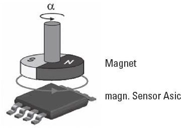
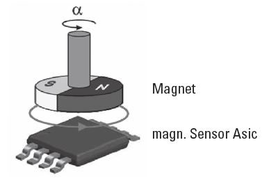
Absolute encoders magnetic scanning
The magnetic field created by a rotating permanent magnet is scanned by a sensor Asic. Each angular position has underlying field vectors, which are converted by the Asic into an electrical signal.
Depending on the version, this output signal can be either SSI, 0ÃÂâÃÂ?ÃÂæ 10V, 4ÃÂâÃÂ?ÃÂæ 20mA or Fieldbus.
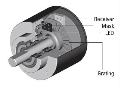
Absolute encoders optical scanning
The light that is emitted by an LED is modulated by a code pattern, which is applied to a rotating disc; this is scanned by a special KuÃÂ?ÃÂèbler Opto ASIC. A unique bit pattern is assigned to each position and this is generally available as Gray Code.
The advantage, compared with incremental encoders, lies in the fact that any movement of the shaft whilst voltage is not applied is immediately detected when power is re-applied, ensuring the correct position is always available.
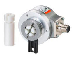
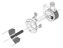
Adapter inserts
By using these adapter inserts you can achieve six different hollow shaft diameters, all on the basis of one encoder.

Adding
The counter starts from zero and counts up to the programmed preset value, at which an output signal is triggered. The counter is then reset to zero - this can be programmed to happen automatically. The current count value is always displayed.
Adding pulse counter
Add the incoming impulses continuously. They are available with or without electrical or manual reset. Miniature counters are also available for battery operation with a power consumption of only 50 or 30 mW and are protected against shock and vibration to a very high extent.
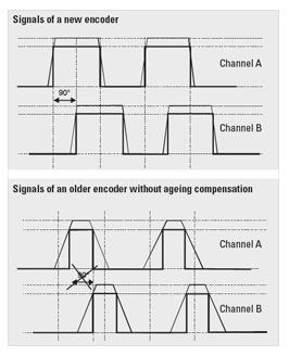
Aging compensation
Every LED loses some of its luminosity over time. Without ageing compensation the excellent quality of the output signals would suffer. The phase shift of 90ÃÂ?ÃÂð necessary to detect the direction of rotation would be lost. This effect however is prevented by means of special electronic circuitry.
Benefit: The ageing compensation circuit ensures the same signal, even after many years of operating time. The downtime of machines will be reduced dramatically and the reliability is increased.
Ambient temperature
Is the permissible temperature within the direct vicinity of the pulse counter. When using the counters in groups, the reciprocal heating must be taken into consideration as this results in an ambient temperature rise. The upper or lower value is only applicable to the rated voltage.
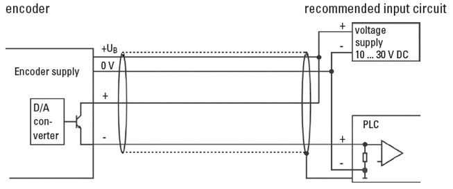
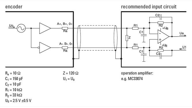
Analogue output 4 ... 20 mA
Output circuit and recommended input circuit
ATEX (ATmosphere EXplosible)
Since 30/06/2003, all new installations used in explosion protected areas have to be built according to the directive 94/9/EG (ATEX 100a).
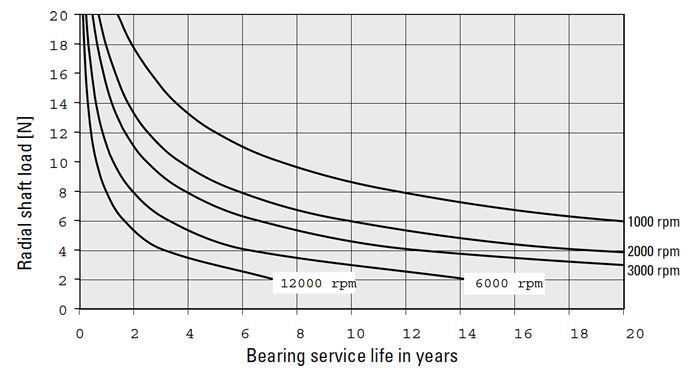
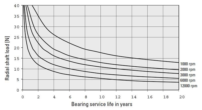
Bearing life
All KÃÂ?ÃÂübler encoders are designed to ensure that their bearings give a long service life. This is subject of course to correct installation and to the load limits for the shaft (shaft encoders) being complied with or, in the case of hollow shaft encoders, being mounted with the appropriate stator couplings or torque stops.
The following diagrams show the expected service life of the shaft encoder bearings depending on the bearing load. The calculations are based on a mixed load, where the axial force components are always half of the radial shaft load.
The use of the torque stops and stator couplings that are offered ensure that the shaft load with the hollow shaft encoders as supplied from the factory is kept very small.
Bearing life for shaft encoders Type 2400
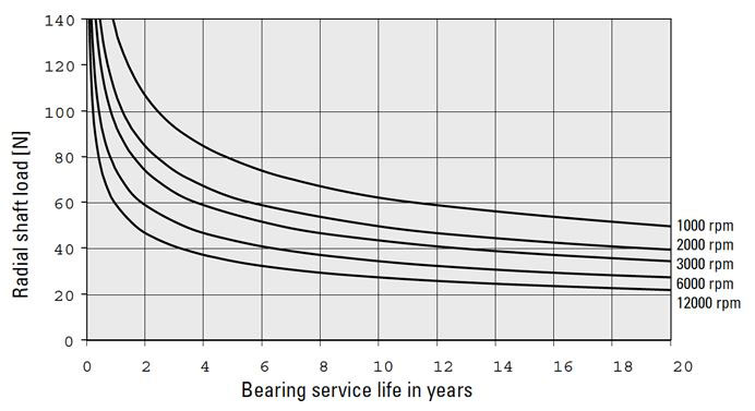
Bearing life for shaft encoders Type 36x0
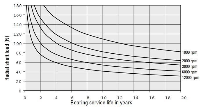
Bearing life for shaft encoders Type 3700
Bearing life for shaft encoders of the Sendix series
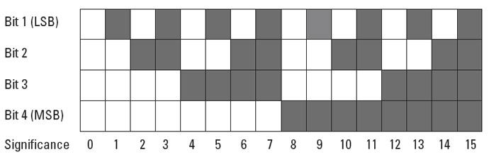
Binary Code
The Binary Code can be processed very easily by computer systems. When using optical read-out, errors may occur, because the change from one bit to another on the different concentric tracks (LSB, LSB+1...) is not exactly synchronized. Due to this, without any correction of the code, the position information could be wrong.
BiSS Interface
Open, digital sensor interface (BiSS-C)
ÃÂâÃÂ?ÃÂâ Easy integration with the assistance of the KÃÂ?ÃÂübler experts team
ÃÂâÃÂ?ÃÂâ The existing standard control hardware can be used
ÃÂâÃÂ?ÃÂâ Open Source
ÃÂâÃÂ?ÃÂâ Real-time feedback of position and speed
ÃÂâÃÂ?ÃÂâ 100 times faster than standard field bus systems
ÃÂâÃÂ?ÃÂâ Fully digital and bi-directional
ÃÂâÃÂ?ÃÂâ The existing standard control hardware can be used
ÃÂâÃÂ?ÃÂâ Open Source
ÃÂâÃÂ?ÃÂâ Real-time feedback of position and speed
ÃÂâÃÂ?ÃÂâ 100 times faster than standard field bus systems
ÃÂâÃÂ?ÃÂâ Fully digital and bi-directional

Bit (Binary Digit)
Smallest discrete piece of information. A bit can be allocated to the value 0 or 1.
Cable lengths for absolute encoders
Cable length: the following maximum cable lengths are recommended, depending on the output circuitry and any noise sources present:
Interface And Output Circuit: Parallel CMOS/TTL
Max. Cable Length: 2 m
Connected To: SPS / IPC (1)
Max. Cable Length: 2 m
Connected To: SPS / IPC (1)
Interface And Output Circuit: Parallel push-pull
Max. Cable Length: 100 m
Connected To: SPS / IPC (1)
Max. Cable Length: 100 m
Connected To: SPS / IPC (1)
Interface And Output Circuit: SSI
Max. Cable Length: Up To 1000 m
Connected To: SPS / IPC (1)
Max. Cable Length: Up To 1000 m
Connected To: SPS / IPC (1)
Interface And Output Circuit: RS 422 /RS 485
Max. Cable Length: 1000 m
Connected To: SPS / IPC (1)
Max. Cable Length: 1000 m
Connected To: SPS / IPC (1)
Interface And Output Circuit: Analogue 4 ... 20 mA
Max. Cable Length: 200 m
Connected To: -
Max. Cable Length: 200 m
Connected To: -
Annotations:
ÃÂâÃÂ?ÃÂâ Depending on the application the max. allowed cable length can be shorter, especially in areas with strong electrical noise.
ÃÂâÃÂ?ÃÂâ Always use shielded cables.
ÃÂâÃÂ?ÃÂâ The core diameter of the signal cores should be ? 0.14 mmÃÂ?ÃÂò.
ÃÂâÃÂ?ÃÂâ The core diameter of the voltage supply cores should be large enough depending on the cable length, that the voltage supply of the encoder is high enough and the signals do not go below the minimum levels!
ÃÂâÃÂ?ÃÂâ We strictly recommend the use of the cable types written down in the accessories.
(1) IPC = Industrial PC
(2) Depends on clock frequency: at 100 kHz Lmax approx. 250 m; at f = 250 kHz Lmax approx. 50 m
(2) Depends on clock frequency: at 100 kHz Lmax approx. 250 m; at f = 250 kHz Lmax approx. 50 m
Cable lengths for incremental encoders
Depending on the output circuit and the electrical noise the following cable lengths are recommended:
Output Circuit: Push-pull without inverted signals
Max. Cable Length: 100 m *
Encoder Connected To E.G: KuÃÂ?ÃÂèbler counter/SPS
Max. Cable Length: 100 m *
Encoder Connected To E.G: KuÃÂ?ÃÂèbler counter/SPS
Output Circuit: Push-pull with inverted signals
Max. Cable Length: 250 m *
Encoder Connected To E.G: SPS / IPC (1)
Max. Cable Length: 250 m *
Encoder Connected To E.G: SPS / IPC (1)
Output Circuit: Push-Pull with inverted signals (7272)
Max. Cable Length: 30 m *
Encoder Connected To E.G: -
Max. Cable Length: 30 m *
Encoder Connected To E.G: -
Output Circuit: RS422 with inverted signals
Max. Cable Length: up to 1000 m (> 50 m dep. on frequency)
Encoder Connected To E.G: SPS / IPC (1)
Max. Cable Length: up to 1000 m (> 50 m dep. on frequency)
Encoder Connected To E.G: SPS / IPC (1)
Output Circuit: Voltage sine with inverted signals
Max. Cable Length: 50 m
Encoder Connected To E.G: SPS / IPC (1)
Max. Cable Length: 50 m
Encoder Connected To E.G: SPS / IPC (1)
Output Circuit: Sine wave 1 Vss
Max. Cable Length: 50 m
Encoder Connected To E.G: 10 ... 30 V DC
Max. Cable Length: 50 m
Encoder Connected To E.G: 10 ... 30 V DC
Annotations:
ÃÂâÃÂ?ÃÂâ Depending on the application the recommended cable length can be shorter, especially in areas with a high level of electrical noise.
ÃÂâÃÂ?ÃÂâ Always use shielded cables - the shield should be connected at both the encoder and controller ends!
ÃÂâÃÂ?ÃÂâ The core diameter of the signal cores should be > 0.14 mm2ÃÂ?ÃÂò.
ÃÂâÃÂ?ÃÂâ The core diameter of the voltage supply cores should be large enough depending on the cable length, that the voltage supply of the encoder is high enough and the signals do not go below the minimum levels!
(1) Depends on frequency
(2) IPC = industrial PC
(2) IPC = industrial PC
Cables material information
PVC
ÃÂâÃÂ?ÃÂâ Suitable for average mechanical stresses in the area of packaging machines and assembly and production lines
ÃÂâÃÂ?ÃÂâ Good resistance against acids and alkalis and thus predestined for use in the food and beverage industry
ÃÂâÃÂ?ÃÂâ Limited friction resistance and partial resistance to oils and chemicals
ÃÂâÃÂ?ÃÂâ Good resistance against acids and alkalis and thus predestined for use in the food and beverage industry
ÃÂâÃÂ?ÃÂâ Limited friction resistance and partial resistance to oils and chemicals
PUR
ÃÂâÃÂ?ÃÂâ Flexible, PVC, silicone and halogen-free control cable with PUR cable jacket and polypropylene wire insulation
ÃÂâÃÂ?ÃÂâ The cable is oil-resistant and non-flammable according to VDE 0472, and it is resistant to chemicals, hydrolysis and microbes
ÃÂâÃÂ?ÃÂâ Temperature resistance from -30ÃÂ?ÃÂðC to + 90ÃÂ?ÃÂðC
ÃÂâÃÂ?ÃÂâ Use is possible in trailing cable carriers with a bending radius equal at least to 10 x D
ÃÂâÃÂ?ÃÂâ Thanks to its resistance to welding sparks, this cable is very well adapted for flexible use in the area of robotics, machine tools and metal cutting production
ccw (counter clockwise)
Turning the encoder shaft in counterclockwise direction (in view of the shaft side of the encoder).
Connection Technology
Connection Technology from KÃÂ?ÃÂübler = System Safety!
All the products in the Connection Technology section have been tested and approved with the relevant compatible KÃÂ?ÃÂübler sensors. They ensure the full functionality and high signal quality of our sensors - this guarantee is supported by our competent customer service.
Your benefit:
ÃÂâÃÂ?ÃÂâ Elimination of connection errors ÃÂâÃÂ?ÃÂ? no laborious fault finding
ÃÂâÃÂ?ÃÂâ Optimal shielding ÃÂâÃÂ?ÃÂ? avoids EMC problems
ÃÂâÃÂ?ÃÂâ Shorter installation times ÃÂâÃÂ?ÃÂ? saves time, cuts costs
ÃÂâÃÂ?ÃÂâ No time-consuming search for the right connector or cable ÃÂâÃÂ?ÃÂ? saves time, eliminates errors
ÃÂâÃÂ?ÃÂâ Optimal shielding ÃÂâÃÂ?ÃÂ? avoids EMC problems
ÃÂâÃÂ?ÃÂâ Shorter installation times ÃÂâÃÂ?ÃÂ? saves time, cuts costs
ÃÂâÃÂ?ÃÂâ No time-consuming search for the right connector or cable ÃÂâÃÂ?ÃÂ? saves time, eliminates errors
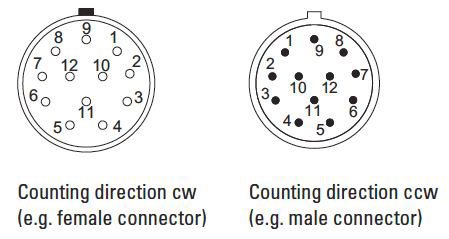
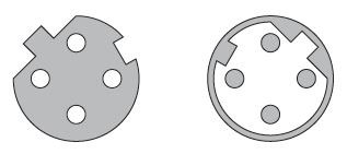
Connectors counting direction cw/ccw
The counting direction of the connectors is indicated by cw for a clockwise arrangement and ccw for a counter-clockwise arrangement. The connector is always viewed from the mating side.
Connectors M12 coding
The connectors are coded to guarantee protection against polarity reversal. This coding is achieved by means of a peg or a notch in the contact carrier. KÃÂ?ÃÂübler connectors make a distinction between A, B or D coding.
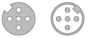
A-Coding
Female connector with coupling nut: Coding notch
Male connector with external thread: Coding peg
Use: CANopen and 8-pin connector
Male connector with external thread: Coding peg
Use: CANopen and 8-pin connector
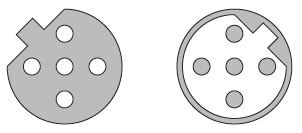
B-Coding
Female connector with coupling nut: Coding peg
Male connector with external thread: Coding notch
Use: Profibus
Male connector with external thread: Coding notch
Use: Profibus
D-Coding
Female connector with coupling nut: Coding peg and Coding notch
Male connector with external thread: Coding peg and Coding notch
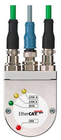
Use: Profinet and EtherCat
Male connector with external thread: Coding peg and Coding notch
Use: Profinet and EtherCat
Connectors material information
Two material groups are used for the connectors described in the catalogue:
Metals for contacts and housings
ÃÂâÃÂ?ÃÂâ Contacts: Metal, CuZn, gilded
ÃÂâÃÂ?ÃÂâ Connecting nut /compression screw: Metal, CuZn, nickel-plated
ÃÂâÃÂ?ÃÂâ Connecting nut /compression screw: Metal, CuZn, nickel-plated
Plastics for insulator and housing
ÃÂâÃÂ?ÃÂâ Contact carrier: Plastic, TPU, black
ÃÂâÃÂ?ÃÂâ Body: Plastic, TPU, black
ÃÂâÃÂ?ÃÂâ Seal: Plastic, fluorine rubber (FKM/FPM) FPM/FKM or nitrile-butadiene rubber (NBR)
ÃÂâÃÂ?ÃÂâ Body: Plastic, TPU, black
ÃÂâÃÂ?ÃÂâ Seal: Plastic, fluorine rubber (FKM/FPM) FPM/FKM or nitrile-butadiene rubber (NBR)
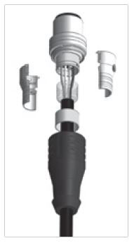
Connectors shielding
With round connectors, care must be taken to connect carefully the shielding braid of the cable to the shield connection of the connector.
An all-round contact (360ÃÂ?ÃÂð) is optimal. Good (in practice often sufficient) shielding values are also reached by connecting the shielding braid firmly to the electrically conductive housing. Connectors purely out of plastic, without metal sleeve, providing no contact for the shielding braid, are not sufficient.
Furthermore, a proper contact with the mating connector is also important, as well as a good contact of the mating connector with the chassis of the equipment.
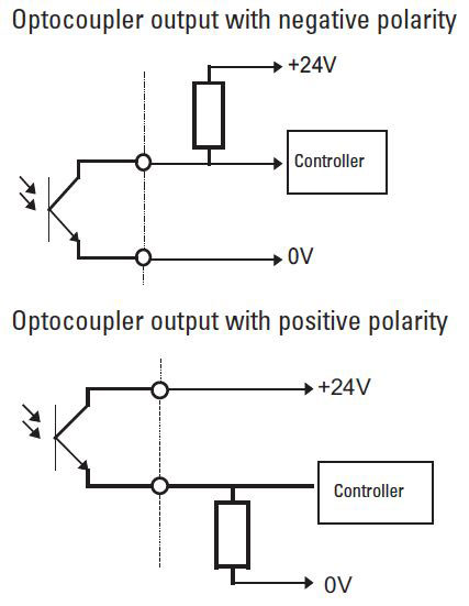
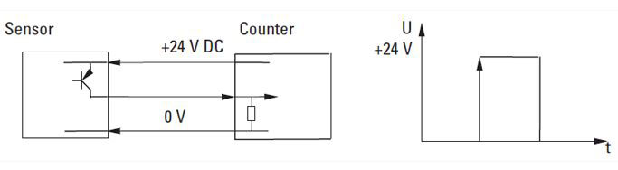
Counter outputs
We offer our preset counters with various output options: relay, transistor and optocoupler.
Relays should not be used when switching very small loads. Transistor or optocoupler outputs are better suited to operate the input of a controller. The design of both outputs is basically almost the same. However with the optocoupler, galvanic isolation is achieved between the unit (counter) and the peripheral (controller) because of an LED and a phototransistor (in one housing).
As a rule, with the optocoupler output the emitter and the collector are brought out and may have to be switched externally. Using the appropriate circuit it is possible to achieve either negative polarity (normally closed function) or positive polarity (normally open function).
cw (clockwise)
Turning the encoder shaft in clockwise direction (in view of the shaft side of the encoder).
Designation of colours
Designation of colours to DIN IEC 757
BK black
BN brown
RD red
OG orange
YE yellow
GN green
BU blue
VT violet
GY grey
WH white
PK pink
GD gold
TQ turquoise
SR siver
BN brown
RD red
OG orange
YE yellow
GN green
BU blue
VT violet
GY grey
WH white
PK pink
GD gold
TQ turquoise
SR siver
Digital outputs
The sine wave signal from the optical system is first digitised to have square wave signals available.
ÃÂâÃÂ?ÃÂâ Shaft turning clockwise, top view of shaft
ÃÂâÃÂ?ÃÂâ Inverted signals are available
ÃÂâÃÂ?ÃÂâ 0 pulse is linked to AND with channel A and B
ÃÂâÃÂ?ÃÂâ Shaft turning clockwise, top view of shaft
ÃÂâÃÂ?ÃÂâ Inverted signals are available
ÃÂâÃÂ?ÃÂâ 0 pulse is linked to AND with channel A and B
To transmit the signals there are two possible outputs available. RS422 (TTL compatible) or push-pull. When choosing the suitable output for the application the following points have to be considered:
ÃÂâÃÂ?ÃÂâ The corresponding unit / controller the encoder will be connected to
ÃÂâÃÂ?ÃÂâ The required cable length
ÃÂâÃÂ?ÃÂâ Dihe sensitivity against electrical noise or other interference
ÃÂâÃÂ?ÃÂâ The required cable length
ÃÂâÃÂ?ÃÂâ Dihe sensitivity against electrical noise or other interference
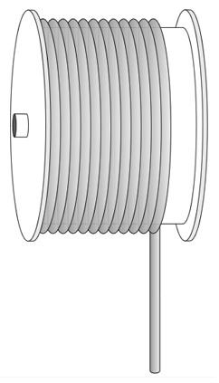
Draw wire system
The idea
At the core of a draw wire encoder is a drum mounted on bearings, onto which a wire is wound. The winding takes place via a spring-loaded device. The number of revolutions is measured by means of an encoder. If the circumference of the drum is known, then the length can be calculated from it.
ÃÂâÃÂ?ÃÂâ Specially for demanding applications
ÃÂâÃÂ?ÃÂâ With analogue sensors (0 ... 10 V, 4 ... 20 mA, potentiometer) or encoders (incremental, absolute, fieldbus)
ÃÂâÃÂ?ÃÂâ Measuring lengths from 250 mm up to 40000 mm
ÃÂâÃÂ?ÃÂâ High travelling speed
ÃÂâÃÂ?ÃÂâ High acceleration
ÃÂâÃÂ?ÃÂâ Dynamic spring traction by means of a constant force spring, long service life
ÃÂâÃÂ?ÃÂâ Simple wire fixing using clip
ÃÂâÃÂ?ÃÂâ Quick mounting
ÃÂâÃÂ?ÃÂâ Diamond-polished ceramic guide
ÃÂâÃÂ?ÃÂâ Titanium anodised aluminium housing
Electrical reset
Counters with electrical reset have an electromagnet which is operated by a reset pulse, and resets the number wheels back to the starting number. With remote reset via a pulse, the pulse duration must be long enough for the reset operation to be completed and for the minimum pulse duration to be maintained in accordance with the technical data of the counters.
It is essential that during resetting no pulses may pass into the count mechanism, as otherwise intermediate positions of the number wheel or slippage of the drive mechanism can occur. There is no danger of mechanical damage of the counter, however.
In order to avoid mistakes, the count pulses should only be allowed to enter, when the number wheels have been accurately adjusted and the drive mechanism is fully engaged. With remote reset a count interval of at least 50 ms after pulse end is required and thus the total count interval = reset pulse time + 50 msec.
Electromechanical pulse counter
The general counter construction consists of an electromagnetic drive and a mechanical kind of number wheel system. Electrical impulses cause a step-by-step revolution of the number wheels.
Encoders
Encoders can be used in applications, where length, positions, speed or an angular position are measured. They transform mechanical movements into electrical signals and can be divided into incremental and absolute measuring systems.
Incremental encoders generate pulses,where the number of pulses can be a measure of speed, length or position.
In absolute encoders, every position corresponds to an unique code pattern, so that even after a power cut the actual position is recognised, when power is re-applied.
In absolute encoders, every position corresponds to an unique code pattern, so that even after a power cut the actual position is recognised, when power is re-applied.
Encoders with one output channel
Encoders with one output channel are used where no direction sensing is needed, e.g. speed control or length measuring.
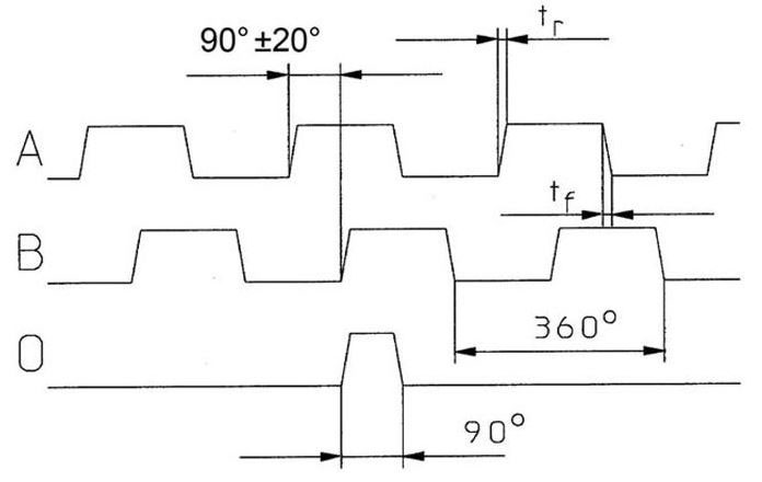
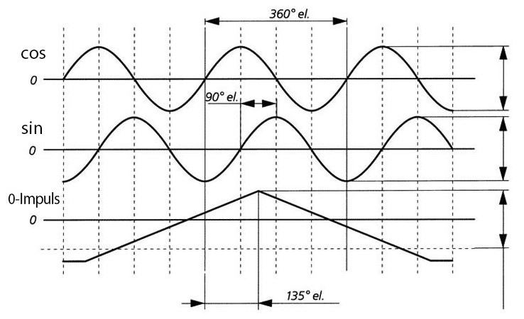
Encoders with three output channels
In addition to the two channels A and B a zero pulse is available, which occurs once per revolution and is usually used for the reference run (zero point calibration) of a machine.
ÃÂâÃÂ?ÃÂâ Shaft turning clockwise, top-view of shaft / for hollow shaft encoders, viewing the flange
ÃÂâÃÂ?ÃÂâ Inverted signals available
ÃÂâÃÂ?ÃÂâ 0 pulse is linked to AND with channel A and B
ÃÂâÃÂ?ÃÂâ Inverted signals available
ÃÂâÃÂ?ÃÂâ 0 pulse is linked to AND with channel A and B
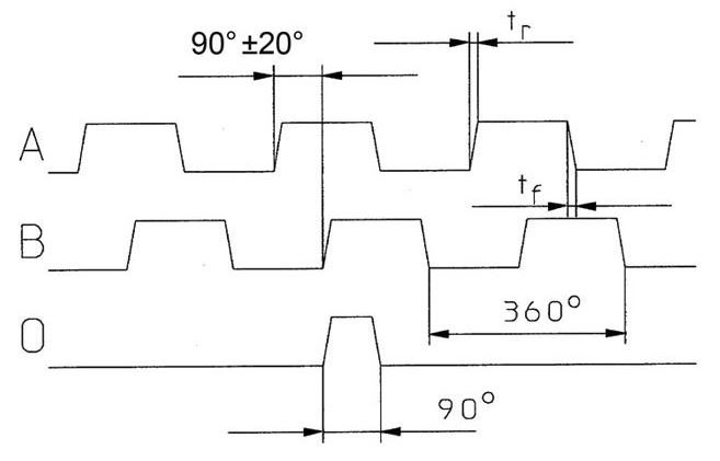
tr = rise time
tf = fall time
Encoders with two output channels
Applications, where the direction of rotation should be sensed, e.g. positioning, require encoders with two channels A and B being shifted 90ÃÂ?ÃÂð out of phase. By detecting the phase shift, the direction can be determined.
ÃÂâÃÂ?ÃÂâ Shaft turning clockwise, top-view of shaft / for hollow shaft encoders, viewing the flange
ÃÂâÃÂ?ÃÂâ Inverted signals available
ÃÂâÃÂ?ÃÂâ Shaft turning clockwise, top-view of shaft / for hollow shaft encoders, viewing the flange
ÃÂâÃÂ?ÃÂâ Inverted signals available
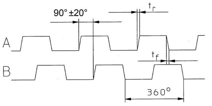
tr = rise time
tf = fall time
Fieldbus
A Fieldbus is an industrial communication system linking numerous sensors and actors to a controlling device.
Functional Safety
KÃÂ?ÃÂübler offers many new products with integrated safety solutions, including:
ÃÂâÃÂ?ÃÂâ Certified SIL2/PLd and SIL3/PLe absolute and incremental encoders
ÃÂâÃÂ?ÃÂâ New safety modules for safe drive monitoring
ÃÂâÃÂ?ÃÂâ New control solutions for safe processing of safety sensors
ÃÂâÃÂ?ÃÂâ New safety modules for safe drive monitoring
ÃÂâÃÂ?ÃÂâ New control solutions for safe processing of safety sensors
KÃÂ?ÃÂübler Safe Drive Monitoring and Safety Control Solutions with certified SIL2/PLd and SIL3/PLe encoders and Safety M modules, featuring:
ÃÂâÃÂ?ÃÂâ Easy realization of the European directive for machine 2006/42/EG
ÃÂâÃÂ?ÃÂâ Simple to integrate on the standard control environment
ÃÂâÃÂ?ÃÂâ User-friendly programming with logic chart and bloc function
ÃÂâÃÂ?ÃÂâ Simple to integrate on the standard control environment
ÃÂâÃÂ?ÃÂâ User-friendly programming with logic chart and bloc function
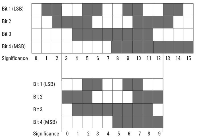
Gray Code
The Gray Code is a single-step code, which guarantees that from one position to the next only 1 bit changes.
This leads to reliable scanning of the code and consequently of the positions.
This leads to reliable scanning of the code and consequently of the positions.
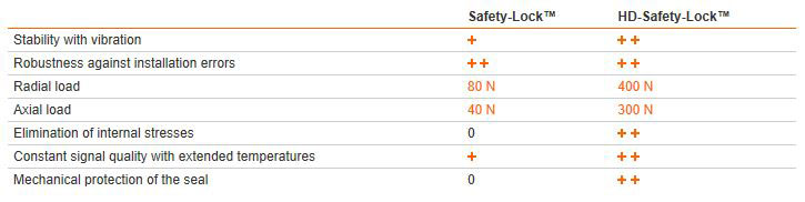
HD-Safety-Lock
Safety-Lock becomes HD-Safety-Lock
Safety-Lock
ÃÂâÃÂ?ÃÂâ mechanically interlocked bearings
ÃÂâÃÂ?ÃÂâ large, extra-strong outer bearings
ÃÂâÃÂ?ÃÂâ larger bearing span
ÃÂâÃÂ?ÃÂâ mechanically interlocked bearings
ÃÂâÃÂ?ÃÂâ large, extra-strong outer bearings
ÃÂâÃÂ?ÃÂâ larger bearing span
Benefits: Avoids premature damage or even encoder failure in the field.
HD-Safety-Lock = Safety-Lock + additional engineering
ÃÂâÃÂ?ÃÂâ Floating bearing on the cover-side eliminates internal stress
ÃÂâÃÂ?ÃÂâ Mechanically decoupled sensor unit ensures constant signal quality with large temperature fluctuations and other adverse environmental influences
ÃÂâÃÂ?ÃÂâ Dual seals on the shaft-side - friction seal against humidity, labyrinth seal against dust and water jet ingress
ÃÂâÃÂ?ÃÂâ Very large, highly-robust flange bearings
ÃÂâÃÂ?ÃÂâ Even greater bearing clearance
Benefits: The resistance against adverse environmental conditions is greatly increased - especially against high bearing loads and high temperatures.
Inclinometers
Inclinometers are used to measure deviations with respect to a horizontal rotary axis on an angular range up to 360ÃÂ?ÃÂð. Kuebler inclinometers are based on the MEMS technology (micro electro-mechanical system).
Incremental encoders magnetic scanning
The magnetic field created by a rotating permanent magnet is scanned by a sensor Asic. Each angular position has underlying field vectors, which are converted by the ASIC into incremental signals.
Incremental encoders optical scanning
A disc fitted with a grating, having a code pattern of slits and bars, is mounted so that it can rotate between an LED and a receiver.
The light emitted by the LED is modulated by the mask and grating and then strikes the receiver, which produces a signal proportional to the luminosity.
When the disc rotates this signal has a shape that approximates to a sine wave.
Installing encoders
Encoders shafts and in turn their bearings are subjected to loads for a variety of reasons:
ÃÂâÃÂ?ÃÂâ Installation tolerances when mounting the encoders (radial and angular displacement)
ÃÂâÃÂ?ÃÂâ Thermal changes, e.g. linear expansion of the drive shaft
ÃÂâÃÂ?ÃÂâ Effects of wear, e.g. radial runout of the drive shaft or vibrations
ÃÂâÃÂ?ÃÂâ Thermal changes, e.g. linear expansion of the drive shaft
ÃÂâÃÂ?ÃÂâ Effects of wear, e.g. radial runout of the drive shaft or vibrations
These load factors have a direct effect on the life expectancy of the shaft bearings and on the quality of the signal. Facilities must therefore be provided during installation to compensate for these forces. For encoders having a solid shaft this is generally done by using shaft couplings between the drive shaft and the encoder shaft. The solution with hollow shaft encoders is to use stator couplings, fixing brackets or torque stops between the encoder flange and the mounting surface.
Not making use of a coupling but instead rigidly mounting the shaft and the encoder housing generally leads to unacceptably high loads on the bearings; the ensuing wear will cause the encoder to fail prematurely.
In order to avoid permanent damage of the encoder, certain bearing loads should not be exceeded. If hollow shaft encoders are correctly installed and the torque stops or stator couplings that are available from KuÃÂ?ÃÂèbler are used, then no problems should occur. For solid shaft encoders the maximum permitted axial and radial loads are shown in the appropriate technical data.
Integrative Technology
Integrative Technology, developed and patented by KuÃÂ?ÃÂèbler, is a package of measures that ensures compact construction, high signal quality, high shock resistance - up to 2500 m/s2, high reliability and a high level of immunity to EMC.
This is achieved using an Opto ASIC, a multilayer board and an especially shock resistant and space-saving method of mounting the sensor unit. In addition the use of a highly optimized interface ASIC ensures the integration of several hundred individual components. Components that had previously been needed to balance the system, such as balancing potentiometers, can be dispensed with.
Advantages of Integrative technology: Singleturn shaft encoders are available with the same dimensions as their incremental correspondents. This allows for easy mechanical substitution.
Intelligent Scan Technology
Firstly all the single and multiturn functions of the encoder are integrated on an Opto ASIC.
With multiturn versions the optical sensor technology can achieve a resolution of up to 41 bits. Furthermore, the new Intelligent Scan Technology ensures 100% magnetic insensitivity.
Sendix F36: The compact revolution
The absolute multiturn and singleturn variants with a size of just 36 mm are able to offer a through hollow shaft diameter of up to 10 mm. The Sendix F36 are the first multiturn encoders with Intelligent Scan Technology.

Intelligent-Sensing-Technology (IST)
An innovative principle of operation based on a non-contact electronic multiturn stage overcomes system disadvantages previously associated with encoders that had mechanical gears or with traditional electronic gear technology.
Advantages
ÃÂâÃÂ?ÃÂâ High operational reliability
ÃÂâÃÂ?ÃÂâ Logic filter and innovative principle of operation compensate for high EMC interface
ÃÂâÃÂ?ÃÂâ Free from wear
ÃÂâÃÂ?ÃÂâ Logic filter and innovative principle of operation compensate for high EMC interface
ÃÂâÃÂ?ÃÂâ Free from wear
Inverted signals
When used in environments, with a lot of electrical noise and/or if very long cable distances are required, we recommend using encoders with inverted (complementary) signals.
These signals are always available with output circuits of the RS422 type and sine wave outputs or optionally with push-pull outputs.
IP protection
The IP classification according to EN 60529 describes how the encoder is protected against particles and water. It is described as an abbreviation ÃÂâÃÂ?ÃÂÃÂIPÃÂâÃÂ?ÃÂàfollowed by two numbers.
These two tables summarise the most used IP ratings.
Protection against particles (first digit)
The higher the number the smaller the particles.
The higher the number the smaller the particles.
0 not protected
1 protected against particles 50 mm and larger
2 protected against particles 12.5 mm and larger
3 protected against particles 2.5 mm and larger
4 protected against particles 1.0 mm and larger
5 protected against dust
6 dust proof
1 protected against particles 50 mm and larger
2 protected against particles 12.5 mm and larger
3 protected against particles 2.5 mm and larger
4 protected against particles 1.0 mm and larger
5 protected against dust
6 dust proof
(Our encoders have a protection up to IP 69k.)
Protection against water (second digit)
The higher the number, the higher the water pressure can be.
The higher the number, the higher the water pressure can be.
0 not protected
1 protected against vertically falling drops of water
2 protected against vertically falling drops of water when enclosure is tilted up to 15ÃÂ?ÃÂð
3 protected against spraying water
4 protected against splashing water
5 protected against water jets
6 protected against powerful water jets
7 protected against the effects of temporary immersion in water
8 protected against the effects of continuous immersion in water
9k according to DIN 40050 / Part 9: protected against high-pressure water/ steam jet cleaning
Isolation inserts
Thermal and electrical isolation of the encoders.
These isolation inserts prevent currents from passing through the encoder bearings. These can occur when using inverter controlled three-phase or AC vector motors and considerably shorten the service life of the encoder bearings. In addition the encoder is thermally isolated as the plastic does not transfer the heat to the encoder.
LCD displays
LCD displays have the advantage of being very economical. They are available in both standard versions and in customised versions.
The advantage of the customised version is that as well as the count value, it is possible to display the preset value and also additional symbols such as, for example, the status of the outputs. With customised models, the height of the digits and the size of the display can be optimally laid out for the corresponding counter.
LCD displays also have the advantage that they are not affected by ambient light and for poorly lit environments they are available with built-in backlighting. Note however that backlit displays do have higher power consumption.
LED
LED = Light Emitting Diode.
LED displays
LED displays are always employed, if units are to be used in environments with diffuse lighting. Due to their self-luminous display, these models are also easy to read even from a long distance.
For each segment, LED displays require a current of between 2 and 10 mA. For a 6 digit counter that could mean from 90 to 450 mA.
A further disadvantage is that no additional symbols can be displayed. As a rule 7 segment displays are the norm, although 14 segment displays or alphanumeric displays can be used to display message texts.
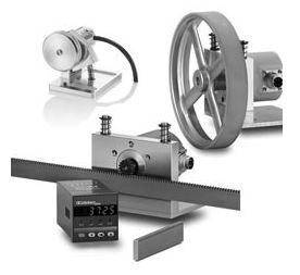
Length measuring kit
We have taken our expertise from the fields of sensor and counting technology and applied this to length measuring kits. We will supply you the measuring wheel, the encoder and the counter ÃÂâÃÂ?ÃÂ? all from one source.
Plug in and go ÃÂâÃÂ?ÃÂ? saves you time and effort ÃÂâÃÂ?ÃÂ? no need to assemble the component parts. We supply the complete kits.
Limes Rotative - Limes Ring
Limes rotative magnetic measuring systems suit ideally for machines and plants with restricted installation space.
The bearingless and contactless measuring principle ensures error-free use in environmental conditions requring high IP protection levels (up to IP69k) and rotary speeds.
Loading of encoder shaft bearings using coupling forces
With all spring couplings (shaft coupling, stator coupling, fixing bracket), alignment and axial errors are converted to a force that corresponds to the spring constant of the coupling. This force has to be absorbed by the encoder shaft bearings. When installing an encoder, this should be done with as little force as possible, i.e. without any unnecessary initial tension on the coupling. If this is adhered to, then with all KuÃÂ?ÃÂèbler couplings adequate tolerance compensation is guaranteed for the whole service life of the encoder bearings.
This force does not occur with torque stops for hollow shaft encoders, where the encoder is prevented from turning also by means of a pin or rod. Although the encoder is prevented from rotating due to a rigid interlock, the encoder is still free to move in any other direction. This is of course dependent on it being mounted in such a way that it has freedom to move radially and especially axially (thermal linear expansion of the drive shaft!).
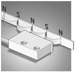
Magnetic measuring system Limes
The idea: A magnetic sensor is guided across a magnetic band without coming into contact with it. The changes in polarity on the magnetic band are counted and intermediate values are interpolated. Our engineers have fine-tuned the system to such a degree that resolutions up to 0.005 mm are possible. The system is not affected by dust, shavings or humidity and is resistant to many liquids and to oil.
Assembly is easy - the magnetic band just has to be glued into place. There are no problems for calibration. The distance between the sensor and the magnetic band can be up to 2 mm. Repeat accuracy is very high.
Where is our LIMES system used?
Where is our LIMES system used?
The measuring system offers an economical alternative to optical systems in applications where the high accuracy of the glass rules is not absolutely necessary but where up till now no other suitable alternative has been available.
Because of its rugged construction the measuring system can now be used even in tough industrial environments. The system is not affected by vibration nor is it damaged if subjected to high shock loads. Our flexible magnetic band offers a further interesting area of application, due to the fact that it can be fitted round very large shafts. The maximum length of the magnetic band is 90 m!
Maximum pulse frequency
Is the maximum possible count frequency which the counter in question can consume in permanent operation. It differs according to counter type and power consumption and is limited by the required pickup- and release times of the counting solenoid.
Mechanical or electronic gears?
Absolute singleturn and multiturn encoders have established themselves as the standard method for measuring linear displacement or angular position. With absolute encoders a reference trip is no longer needed after system start-up or a power-down.
Multiturn encoders in particular are now being employed, where previously incremental encoders had predominated, for example with geared motors or in lifts.
Today all manner of multiturn encoders are available in a variety of designs. As a rule the manufacturers offer either mechanical gears for ÃÂâÃÂ?ÃÂ?counting turnsÃÂâÃÂ?ÃÂ?, or swear by electronic counters with electronic data storage. They are critical of any other technology. The fact is however: it is not a case of which is better or worse; each technology has its advantages and drawbacks. Only the actual application can decide.
Minimum pulse interval
Is the period of time which is sufficient for accurate counting. Optimal spark quenching is imperative if high count frequency is required.
Minimum pulse on time
Is the period of time which is sufficient for accurate counting, even at permissible ÃÂ?ÃÂñ variation of operating voltage; the pulse interval can be optionally as long as required.
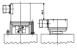
Mounting examples for shaft encoders with clamping bracket
Mounting with an angular bracket and coupling (to reduce shaft overload).
Mounting with a commonly used clamping device and coupling (to reduce shaft overload).
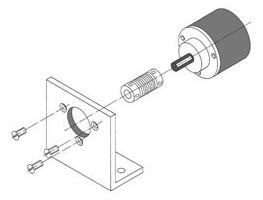
Mounting examples for shaft encoders with synchronous flange
Mounting with fastening eccentrics and coupling (to reduce shaft overload).
Mounting with assembly bell, fastening eccentrics and coupling (to prevent shaft overload and to isolate the encoder thermally and electrically).
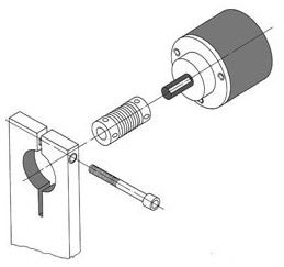
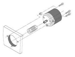
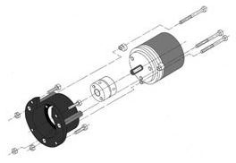
Mounting options for hollow shaft encoders
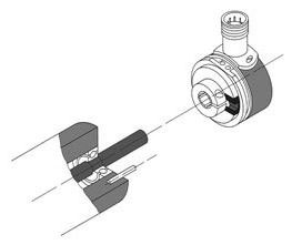
Mounting of a hollow shaft encoder with torque stop and pin (easiest and fastest mounting). Standard hollow shaft encoders are equipped with the torque stop. (Cylindrical pin not supplied.)
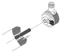
Mounting of a hollow shaft encoder with extended torque stop and long pin.
Mounting of a hollow shaft encoder with a stator coupling.
Multiplication of pulses
The resolution of a two channel encoder can be multiplied by two or four using special edge detection circuitry.
An encoder with physically 5000 pulses per revolution can generate 20000 pulses per revolution using this technique.
An encoder with physically 5000 pulses per revolution can generate 20000 pulses per revolution using this technique.
Multiturn encoders
Up to 17 Bit unique angular positions per revolution are provided. In addition the number of revolutions is detected. Up to 4096 (12 Bit) unique revolutions can be made available on the output.
Multiturn encoders are suitable for angular measurement over more than one turn of a shaft, for example with longer traverse paths, such as high rack storage areas, cranes or machine tools.
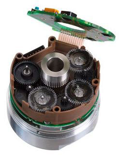
Multiturn stage with gear
ÃÂâÃÂ?ÃÂâ Multiturn gear with purely optical scanning technology. Completely resistant to magnetic fields.
ÃÂâÃÂ?ÃÂâ First stage with double bearing layer
ÃÂâÃÂ?ÃÂâ Special materials ensure temperature stability and long service life
ÃÂâÃÂ?ÃÂâ Through hollow shaft diameter up to 14 mm - up to 15 mm as blind hollow shaft
ÃÂâÃÂ?ÃÂâ Specially developed gear teeth allow for very high rotational speeds and eliminate wear.
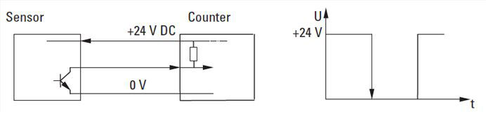
Negative input polarity (NPN)
On time ED
States how long a coil may be energized without overheating. The following formula is applicable:
ED % = (pulse on time/(pulse on time + pulse interval)) x 100
From this can be derived:
pulse on time = (ED %/100 - ED %) x pulse interval
pulse interval = (100 - ED %/ED %) x pulse on time
In addition to the ED % figure the listed values include an addition concerning the maximum permanent on time.
Therefore a coil may only be energized by a constant current during this period and then has to be cooled off again.
At ED = 100% a limitation is not necessary as the coil will never become inadmissibly hot, even if continuously energized.
Example:
A count coil has the listed value ED = 15 %, max. 55 sec. This coil may therefore remain under constant current for max. 55 sec. After this a cooling interval of pulse interval = ((100-15)/15) x 55s = 283s is required.
The same coil is constantly receiving pulses of 40 sec. duration with a count interval of 6 min. Is this still permissible?
ED % = (40/40 + 360) x 100 = 10 %
Result:
Since the on time does not exceed 15 % these pulse-on times are permissible.
Since the on time does not exceed 15 % these pulse-on times are permissible.
Operating temperature
Is defined as the environmental temperature, in which the encoder can be operated without incurring damage.
Optical fibre signal transmission general information
The system is made up of an optical fibre transmitter and an optical fibre receiver. The optical fibre transmitter converts the electrical signals of an encoder into optical fibre signals. A simple glass fibre allows reliable transmission up to distances of 1500 m. The receiver module converts the optical signals back into electrical signals. The modules are also available in various level and power supply voltage variants.
Main advantages of an optical fibre transmission:
ÃÂâÃÂ?ÃÂâ Insensitivity to electromagnetic interferences and to leakage effects between lines routed parallel
ÃÂâÃÂ?ÃÂâ Significantly higher transmission speeds
ÃÂâÃÂ?ÃÂâ The optical fibre cable can be routed through explosive atmospheres
ÃÂâÃÂ?ÃÂâ Cost and weight savings thanks to reduced cabling work, especially for important cable lengths
ÃÂâÃÂ?ÃÂâ Significantly higher transmission speeds
ÃÂâÃÂ?ÃÂâ The optical fibre cable can be routed through explosive atmospheres
ÃÂâÃÂ?ÃÂâ Cost and weight savings thanks to reduced cabling work, especially for important cable lengths
Optical fibre signal transmission glass fibre cables
The modules can be connected together using 50/125 ÃÂ?ÃÂõm or 62,5/125 ÃÂ?ÃÂõm multimode glass fibre cables with ST/PC type connectors with bayonet catch. Single-mode Simplex patch cables are not suitable.
KÃÂ?ÃÂübler offers finished confectioned patch cables adapted to the optical fibre modules as accessories.
They ensure the full functionality and high signal quality of our sensors.
They ensure the full functionality and high signal quality of our sensors.
Optical fibre signal transmission mounting
The optical fibre modules can be mounted directly on a TS35 DIN rail (top-hat rail) according to EN 50022. The installation width for every module is only 22.5 mm.
Laying and connection of glass fibre cables
Laying the cable is generally easy. Care must nevertheless be taken to make sure that the bending radius does not become smaller than 30 mm for static laying and 60 mm for dynamic laying. When connecting the cable, make sure that the bayonet catch is locked and remove the dust protection caps only just before connecting the cable.
Parallel output
This type of transfer is very fast. All bits of a position are transferred simultaneously each via a separate line.
Output circuit and recommended input circuit
Particular shaft loading due to toothedwheels, gear-pulleys and similar elements
Measuring wheels, toothed wheels or gear pulleys, which are mounted directly on the encoder shaft, exert radial forces on the latter, dependent on prestressing and angular acceleration. KÃÂ?ÃÂübler encoders are designed so that they can absorb these forces to a great extent. The maximum permissible load capacity of the shaft is shown in the technical data for the encoder.
If these load values may be exceeded in a particular application, then the encoder shaft must be isolated from the radial load by interposing an appropriate shaft with its own bearings that can absorb the forces. KÃÂ?ÃÂübler offers suitable bearing blocks and bearing boxes for this purpose (you may also refer to the Accessories section in our catalogue).
Position Display
Position displays are devices, which measure pulses from rotary encoders or linear measurement systems, with incremental pulses or absolute position data. These displayed position values can be scaled using pulse weighting, which means that the display can be converted to any desired magnitude.
Quadrature x1, x2 or x4 input pulse evaluation is available on displays that have incremental inputs. Absolute systems are evaluated using the SSI protocol; singleturn as well as multiturn systems can be displayed and evaluated.
Our SSI display has a fast clock frequency up to 1MHz, suitable for our absolute encoders. It has numerous programmable measurement functions, a scalable display and a scalable analogue output; there is also a version with serial interface and a version with 2 limit values (alarms).
Positive input polarity (PNP)
Possible errors in accuracy due to couplings
1. Deviations in accuracy caused by torsion of a spring coupling (in particular shaft couplings).
This deviation in accuracy is defined by the torque to be transmitted (bearing friction and mass moment of inertia) and by the torsional spring constant of the torque stop.
This deviation in accuracy is defined by the torque to be transmitted (bearing friction and mass moment of inertia) and by the torsional spring constant of the torque stop.
The following applies: Max. error (degree) = max. torque [Ncm] / torsional spring constant [Ncm/Grad]
The following table serves to estimate the ratio between such an error and the smallest increment of an encoder:
Relationship between the resolution of an encoder in bit and the smallest increment in angular degrees:
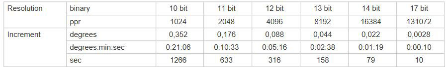
2. Deviations in accuracy caused by radial play in the drive shaft with asymmetrical mounting of the couplings.
Here one has to differentiate between couplings that are mounted in an axially symmetrical manner round the shaft (all shaft couplings, many stator couplings) and asymmetrically mounted couplings (many stator couplings, all mounting brackets and pin-based torque stops).
Here one has to differentiate between couplings that are mounted in an axially symmetrical manner round the shaft (all shaft couplings, many stator couplings) and asymmetrically mounted couplings (many stator couplings, all mounting brackets and pin-based torque stops).
With asymmetrical couplings deviations in accuracy can arise due to radial movements of the drive shaft (radial runout/play); this is determined by the system. These deviations are dependent on the amount of the radial play and the distance of the torque stop locating point from the drive shaft.
The relationship is shown in the following diagram:
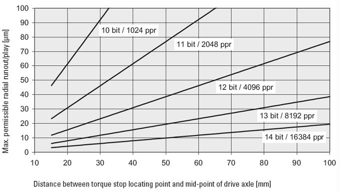
Maximum permissible radial runout to achieve an accuracy >1/2 LSB when using an asymmetrical 1 point torque stop
Preset Counter
It is always the job of preset counters to trigger a signal at a particular count value. In the simplest instance this can mean just shutting down a machine, however it could also be the initialisation of control functions (e.g. cutting material to length, transporting parts etc.). Relays, transistors or optocouplers are used as outputs.
Relays are suitable for switching heavy loads (up to 2000 VA). The actual switching capacity depends on the model (counter) and can be seen in the data sheet. Most relays are available with a changeover function.
Preset Timer
With the preset timers, one or two outputs are additionally available as relay or optocoupler outputs. A particular output is activated, as soon as a pre-selected value is reached. This can occur both in adding or subtracting mode. The signal duration is programmable either as a momentary (timed) pulse or as a maintained (latched) pulse.
Process controllers with an analogue input
For many measuring operations, a digital signal acquisition is too inaccurate or too expensive. This is why analogue signal acquisition is often used in industrial environments. This includes for example temperature, weight (mass), pressure, filling level, volume (flow), speed, acceleration, position and many others. The sensor signals are mostly very small (in the mV or ÃÂ?ÃÂõV range).
The KÃÂ?ÃÂübler Process Controllers amplify these signals, correct possible errors and send them to the display. Process measuring transducers convert these signals into standard signals (e.g. 0 ... 10 V or 4 ... 20 mA). These signals can then be processed further and/or displayed. In addition it is possible to transmit the standard signals over larger distances. Many sensors do not supply a linear output signal. The KÃÂ?ÃÂübler process displays linearise these signals with up to 32 control points, depending on the version.
Processing of the signals
The sine wave signals are then processed in a specially designed electronic circuitry. Most controllers require square-wave signals on their input.
The signals are therefore pre-processed accordingly in the encoder and made available using various output circuits depending on the application.
Pt and Ni resistance sensors
Temperature measurement with resistance sensors uses the temperature sensitivity of metal resistances.
A constant current is applied to the measuring resistance. The voltage drop at the resistance is measured. This drop represents the temperature measurement.
Pulse Counter
These counters have no outputs activated at a specific count value. They are used purely to monitor the count value. The functions range from simple totalizing up to position display (with phase discriminator). Depending on the speed of the events being counted, the count speed can go up to 100 kHz. More recent counters have a scale factor, which for example could be used to convert a length measured in inches into meters.
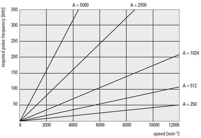
Pulse frequency
The required pulse frequency can be calculated as a result of the number of pulses per revolution (PPR) and the maximum speed (RPM). The maximum pulse frequency is shown in the data sheet specifications for each encoder. Generally this is 300 KHz, but can be up to 800 KHz with high-resolution encoders.
Example:
given:
- Speed n = 3000 min-1
- Resolution of the encoder A = 1000 Imp./U.
- Speed n = 3000 min-1
- Resolution of the encoder A = 1000 Imp./U.
wanted:
- Required pulse frequency of the encoder
- Required pulse frequency of the encoder
fmax = (nxA)/60
The required pulse frequency is thus 50 KHz.
This can now be compared with the maximum possible pulse frequency of the desired encoder.
The required pulse frequency is thus 50 KHz.
This can now be compared with the maximum possible pulse frequency of the desired encoder.
This diagram can be used to estimate the required pulse frequency:
Pulse generators
Appropriate pulse generators are required in order to achieve accurate count results. In this connection, it should be ensured that these operate as far as possible without bounce; this is particularly important for counters with high pulse rate.
Cam operated spring contacts, limit switches and microswitches are suitable for count speeds up to approx. 10 or 25/cps, small relay contacts up to approx. 40 cps, higher count speed up to 60/cps. can be achieved with reed switches, exact matching of spark quenching being necessary to avoid premature sticking of contact reeds. Even higher speeds can be obtained by using photoelectric or inductive sensors. Our pulse generators which are manufactured in a robust and solid style are suitable for count speeds up to maximum of 60/cps.
Pulse ratio
Is the ratio of pulse on time/pulse interval at maximum count frequency.
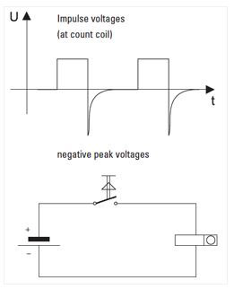
Pulse voltages
DC voltage pulses without or with very small residual ripple are, for example, taken from a battery, DC generator, electronically stabilised power supply, according to the circuit above.
These pulses are most suitable for the maximum possible frequencies due to their ideal square shape. If only AC voltage is available it must be rectified.
Therefore, according to count speed, a more or less greater degree of residual ripple has to be put up with.
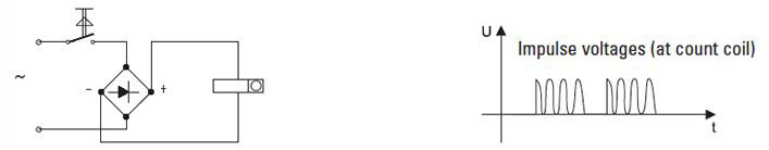
A simple bridge-rectifier will give a residual ripple of approx. 50%, and the following relationship is applicable:
AC voltage (effective value) 12 24 48 60 110 220 V
DC voltage (arithm. mean value) 8,5 19,5 40 49 91 185 V
Two types of switching circuits can be used to drive the counters.
a) Pulse contact in AC circuit Model a0 or a
This circuit is mostly used when the count speed is ? 18 Imp/sec.
Advantage:
No spark required; contact bounces have no negative effect because the rectifier acts as spark quenching and provides inductive drop-out time lag.
Disadvantage:
Count speed only possible up to max. 18 Imp/sec.
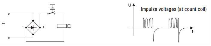
b) Pulse contact in DC circuit version b
Advantage:
High count speed = 25 /cps, only one rectifier is necessary when driving several counters.
Disadvantage:
More sensitive to contact bounce, spark quenching is required.
4 connection points required in rectifier built into counter
With pulse speeds 30 Imp/sec smoothed DC must be used. The residual ripple (smoothing degree) is determined by the count speed and is stated in the technical specification.
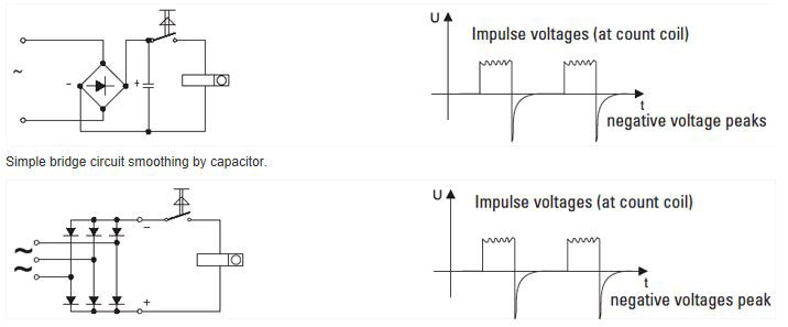
If the rectifiers are connected directly to AC mains they are often damaged through the contamination of the high peak voltages.
These peak voltages are caused by the switching of transformers, spot welding machines, switching motors on and off etc; they often exceed the mains voltage by many times. Therefore it is essential to use a heavy duty rectifier or one with suppressor circuit, so that these peak voltages will not have any destructive effects in the long run.
This is particularly important in the case of silicon rectifiers which are very sensitive to short period excess voltages. It is advisable to use controlled avalanche silicon rectifiers for this purpose. Rectifiers which we build in or attach to our pulse counters have to a large extent, a high dielectric strength, and an over voltage protection is provided, if required.
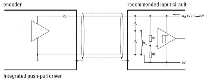
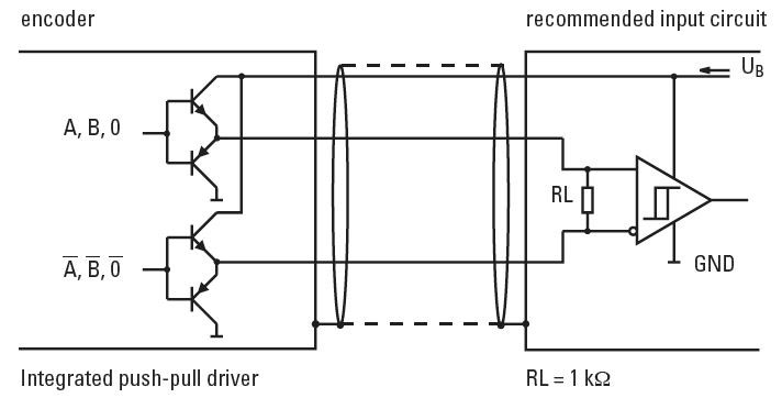
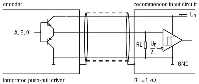
Push-pull outputs
Push-pull outputs are suitable for count interface cards, electronic counters or PLC inputs. They are available in two versions:
Push-pull:
ÃÂâÃÂ?ÃÂâ Push-pull with integrated wave impedance adjustment, recommended cable impedance 40 ... 150 ?
ÃÂâÃÂ?ÃÂâ Recommended for long cable lengths, high pulse frequencies and output voltages to 30 V
ÃÂâÃÂ?ÃÂâ With or without inverted (complementary) signals
ÃÂâÃÂ?ÃÂâ Push-pull with integrated wave impedance adjustment, recommended cable impedance 40 ... 150 ?
ÃÂâÃÂ?ÃÂâ Recommended for long cable lengths, high pulse frequencies and output voltages to 30 V
ÃÂâÃÂ?ÃÂâ With or without inverted (complementary) signals
Push-pull (7272):
ÃÂâÃÂ?ÃÂâ Universal line driver 5 ÃÂâÃÂ?ÃÂæ 30 V with low-level (max 0.5 V)
ÃÂâÃÂ?ÃÂâ Recommended for cable lengths up to 30 m
ÃÂâÃÂ?ÃÂâ With inverted signals
ÃÂâÃÂ?ÃÂâ Universal line driver 5 ÃÂâÃÂ?ÃÂæ 30 V with low-level (max 0.5 V)
ÃÂâÃÂ?ÃÂâ Recommended for cable lengths up to 30 m
ÃÂâÃÂ?ÃÂâ With inverted signals
Push-pull with inverted signals
Push-pull without inverted signals
Residual ripple
Is the AC voltage superposed on the DC voltage in % (Uw/Ug)x100%.
Uw = Effective value of superposed AC voltage.
Ug = arithmetical mean value of DC voltage.
Uw = Effective value of superposed AC voltage.
Ug = arithmetical mean value of DC voltage.
Resolution
The required angular or linear resolution of a application determines the number of pulses per revolution. Linear movements must first be converted into rotary, for example by means of a spindle.
Example:
An encoder is equipped with a measuring wheel. Every revolution corresponds to a distance of 200 mm (circumference). The accuracy should be 0.1 mm. What is the required resolution (ppr)?
An encoder is equipped with a measuring wheel. Every revolution corresponds to a distance of 200 mm (circumference). The accuracy should be 0.1 mm. What is the required resolution (ppr)?
given:
ÃÂâÃÂ?ÃÂâ Circumference of the measuring wheel: U = 200 [mm]
ÃÂâÃÂ?ÃÂâ Accuracy of the system: G = 0,1 [mm]
ÃÂâÃÂ?ÃÂâ Circumference of the measuring wheel: U = 200 [mm]
ÃÂâÃÂ?ÃÂâ Accuracy of the system: G = 0,1 [mm]
wanted:
ÃÂâÃÂ?ÃÂâ Resolution of the encoder: A = ? [pulses/resolution]
ÃÂâÃÂ?ÃÂâ Resolution of the encoder: A = ? [pulses/resolution]
Resolution = Circumference/Accuracy = U/G
The required resolution would be 2000 ppr (pulses per revolution).
Reversion of the Gray Code
The code values increase when the shaft is turning clockwise.
The Gray code is reversible, i.e. if the most significant bit (MSB) is inverted, the code values decrease when the shaft is turning clockwise.
RoHs
KÃÂ?ÃÂübler is active worldwide and has made a commitment to protecting the environment. Our products comply with the RoHS standards.
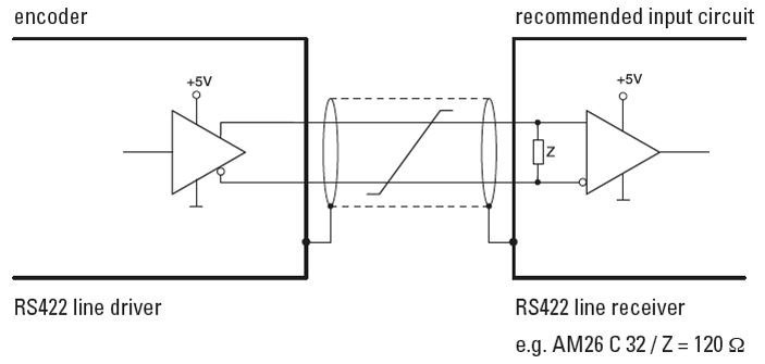
RS422 output/input circuit
RS485 interface
Output circuit and recommended input circuit
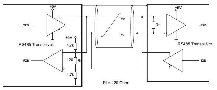
Encoders with internal termination have a fixed terminating resistor Rt built in. This variant is designed for point-to-point transmissions between 2 devices.
With devices having external termination the user must activate the terminating resistor by placing a jumper between pins 5 and 6. This option is suitable to the construction of bus systems with several encoders.
With bus systems, the EIA-485 standard recommends terminating each end of a data link circuit with a terminating resistor. The RS485 interface is asynchronous. In half duplex operation it is not possible to send and receive at the same time. The data transmission is controlled via ESC commands.
Safety-Lock
Interlocked bearings, large bearing span and extra strong outer bearings ensure stability when subjected to vibration and tolerance of installation errors. Machine downtime and repairs are eliminated.
Safety-Lock plus
The proven Safety-Lock construction with additional mechanically protected shaft seal.
Sensor outputs
With long cable runs, the inherent resistance of the cables can lead to a situation where insufficient supply voltage is available to the encoder. Push-pull outputs Push-pull outputs are suitable for count interface cards, electronic counters or PLC inputs. They are available in two versions: Using the sensor outputs of the encoder, the voltage present can be measured and if necessary increased accordingly.
Serial Interface RS 232
The serial interface RS 232 is a full-duplex point-to-point connection. Full-duplex means that data can be both transmitted and received simultaneously via the interface and that only two devices can be connected with each other. If two devices are to be connected to a computer, then a second interface port is required on the computer. The two connections are totally independent from each other. This method has a disadvantage, because interface cards for PLCs are expensive and with PCs a maximum of 4 ports are available for use. For this reason, more recent KÃÂ?ÃÂübler counters are equipped with either the RS 422 or the RS 485 interface. At least a 3-wire cable is needed when connecting RS 232. The connection then works without handshaking. For connections with handshaking a 5-wire cable is needed.
Serial Interface RS 422
This interface is a full-duplex multi-point connection. This means that several receivers can be connected to one transmitter cable. In counting technology the PC or the PLC are used as the master station, which then controls all activity on the serial line. All devices 'listen' to what the master is transmitting, but only that device, which is being addressed, answers. A message can only be sent from one device to another via the master - which does not make much sense with counters. Connecting the PC standard RS 232 port to the RS 422 counter interface is done by means of a simple interface converter. By using this solution, up to 10 devices can be connected to the serial port of a PLC or PC. The wiring is done using a 4-wire cable with all the devices being connected in parallel. Each device has to be assigned a unique address, so that it can distinguish between messages being sent to its own address and those for another address.
Serial Interface RS 485
This interface is a half-duplex multi-point connection. Half-duplex means that the data exchange works in both directions, but only in one direction at a time. It also means that one can transmit and receive over the same line.
Converting the common RS 232 interface to RS 485 is not so easily done. However several devices can act as masters as well as also being receivers (slaves). In total up to 32 devices can be connected to one interface. When connecting the stations together, only a two-wire cable is necessary.
Most fieldbuses operate on this interface basis. The hardware is thus always the same, it is only the protocol that differs - this says which device is being addressed, which information is for that device and what control information is required to check that the transmission has been done correctly.
Setpoint generator
The set-point generator/adjuster triggers a standard signal or a freely programmable signal sequence from 0 ... 12 V or from 0 ... 24 mA.
The set-point generator / adjuster is a real innovation opening up new application potentials in process technology and automation.
The set-point generator / adjuster is a real innovation opening up new application potentials in process technology and automation.
Shaft isolation
Shaft isolation - Protection against bearing damages
Even well-earthed machine housings and rotors of generators and large motors carry a shaft current on the rotor.
The equipotential bonding from the rotor to the stator via the encoder bearings leads to spark erosion and damages the ball bearings. This can be remedied by isolating the encoder bearings.
The equipotential bonding from the rotor to the stator via the encoder bearings leads to spark erosion and damages the ball bearings. This can be remedied by isolating the encoder bearings.
Isolating sleeves can be used for all Sendix compact encoders.
The Sendix H120 has a completely isolated bearing structure and has been tested for a breakdown voltage of 2.5 kV.
Short-circuit protection
The outputs of all the encoders are short-circuit protected, provided that the supply voltage is correctly wired. If an output is connected by mistake to 0 V or +UB or with another output, the device will not be damaged. As soon as the error is corrected, the encoder is ready for use again.
Benefit:
Wiring circuit errors during installation that often occur in the hectic of day-to-day industrial environments do not lead to the encoder being permanently damaged.
Sine wave outputs
The sine wave signals are available as voltage signals. They can be further processed in the evaluation electronics. Due to the interpolation of the two signals, which are 90ÃÂ?ÃÂð out of phase, a very high resolution can be achieved.
Further they are very suitable for digital drives with a very slow movement, e.g. for grinding machines or lifts and elevators.
Shaft turning clockwise, top view of shaft
0 pulse is generated once per turn
0 pulse is generated once per turn
Sine wave voltage output/input circuit
Singleturn encoders
Depending on the number of divisions they generate unique positions per revolution. After one complete revolution the process re-commences at the start position.
They are suitable for angular measurement over a maximum of one turn of the shaft (=360ÃÂ?ÃÂð), for example in robotics, with cam controllers and in other controlled rotary motion.
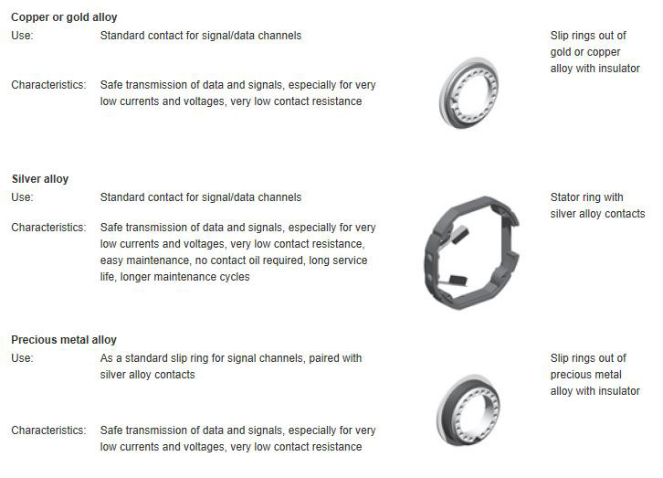
Slip Rings contact materials
Contact materials and characteristics
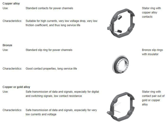
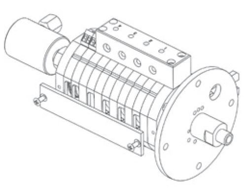
Slip Rings general information
Slip rings are basically used for transmitting electrical current, signals or data, pneumatics and hydraulics from a stationary to a rotary platform.
In slip rings, the electrical transmission between the stator and rotor units takes place via sliding contacts and is extremely reliable.
KÃÂ?ÃÂübler slip rings feature a particularly rugged compact design, long maintenance cycles and a long service life.
The SR085 family has a modular construction and offers highest flexibility for a wide variety of applications.
Slip Rings maintenance
Maintenance
Regular and appropriate maintenance is determining for the safety and service life of the slip ring.
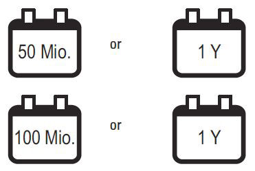
Unless otherwise specified in the technical data sheet, the following maintenance intervals apply:
ÃÂâÃÂ?ÃÂâ Max. 50 million revolutions or min. once yearly
ÃÂâÃÂ?ÃÂâ Only for the contact material silver alloy: every subsequent maintenance interval max. 100 million revolutions or min. once yearly
Unless otherwise specified in the technical data sheet, the following maintenance intervals apply:
ÃÂâÃÂ?ÃÂâ Max. 50 million revolutions or min. once yearly
ÃÂâÃÂ?ÃÂâ Only for the contact material silver alloy: every subsequent maintenance interval max. 100 million revolutions or min. once yearly
Maintenance plan
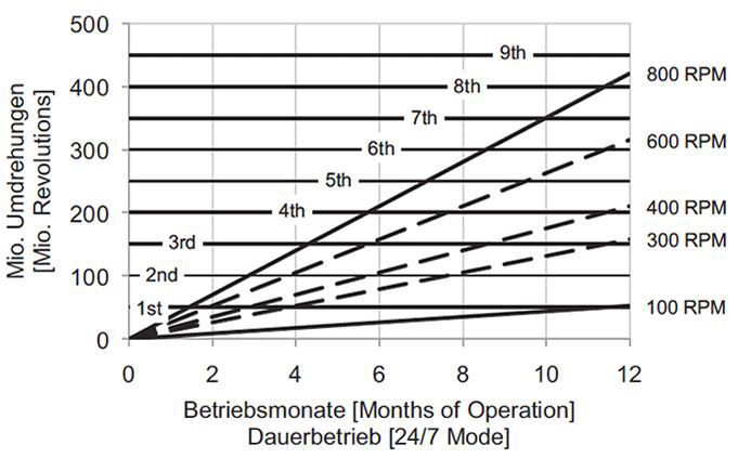
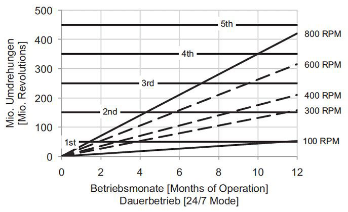
Depending on the rotational speed and on the operating mode, the specified maintenance intervals are reached more or less quickly. In case of continuous operation and corresponding rotational speeds, maintenance will be required, depending on the contact material of the signal/data channels, after the following number of months of operation.
Signal/data channels, contact material gold alloy
Signal/data channels, contact material silver alloy
Position of the maintenance window
Slip ring with maintenance window at the bottom (slip ring for power current up to 16 A)
Slip ring with maintenance window at the bottom (slip ring for power current up to 16 A)
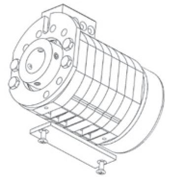
Slip ring with maintenance window on the side (slip ring for power current over 16 A)
Note:
The accurate description of the maintenance work can be found in the respective maintenance instructions.
The accurate description of the maintenance work can be found in the respective maintenance instructions.
Slip Rings mounting
Hollow shaft mounting
ÃÂâÃÂ?ÃÂâ Slide the slip ring on the hollow shaft
ÃÂâÃÂ?ÃÂâ Tighten the setscrews and secure them with screw stop varnish
ÃÂâÃÂ?ÃÂâ Secure the slip ring against rotation with the torque stop
ÃÂâÃÂ?ÃÂâ Slide the slip ring on the hollow shaft
ÃÂâÃÂ?ÃÂâ Tighten the setscrews and secure them with screw stop varnish
ÃÂâÃÂ?ÃÂâ Secure the slip ring against rotation with the torque stop
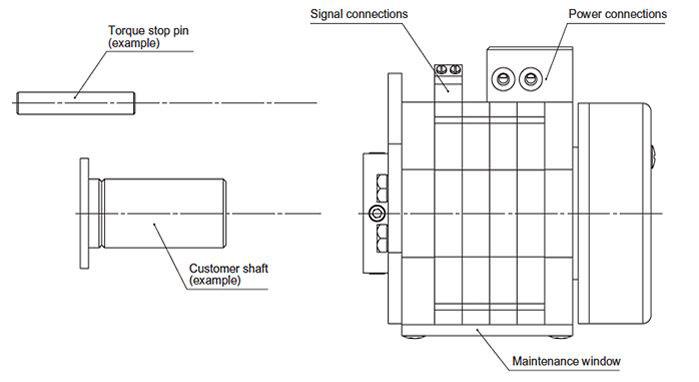
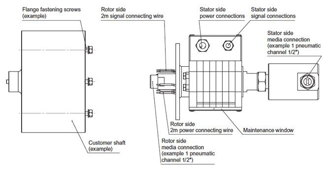
Flange mounting
ÃÂâÃÂ?ÃÂâ Connect the electrical and pneumatic transmission
ÃÂâÃÂ?ÃÂâ Fasten the flange with the screws and secure the screws with appropriate means, e.g. spring washers, screw stop plates
ÃÂâÃÂ?ÃÂâ Secure the slip ring against rotation with the torque stop
ÃÂâÃÂ?ÃÂâ Connect the electrical and pneumatic transmission
ÃÂâÃÂ?ÃÂâ Fasten the flange with the screws and secure the screws with appropriate means, e.g. spring washers, screw stop plates
ÃÂâÃÂ?ÃÂâ Secure the slip ring against rotation with the torque stop
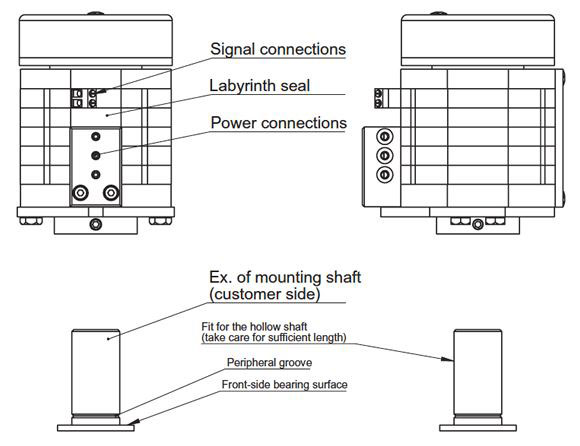
Mounting position
The slip rings of the SR085 and SR060 series can be configured for the following electrical transmissions:
ÃÂâÃÂ?ÃÂâ Only signal transmission
ÃÂâÃÂ?ÃÂâ Only power current transmission
ÃÂâÃÂ?ÃÂâ Mixed transmission of signals and power
ÃÂâÃÂ?ÃÂâ Only signal transmission
ÃÂâÃÂ?ÃÂâ Only power current transmission
ÃÂâÃÂ?ÃÂâ Mixed transmission of signals and power
In the latter case, for a vertical installation, care must be taken so that the signal rings are always located on top. This reduces the possible risk of contaminating the signal contacts. The slip rings of the SR085 series may be installed standing, horizontally and suspended. A distinction is thus made among the installation positions in order to minimize the contamination of the signal channels. The slip rings of the SR060 series are designed only for horizontal or suspended installation.
The mounting position is to be defined in the order code as follows:
IST-SR085-XX-XX-XX-X1XXX-VXXX, in case of standing and horizontal installation (flange at the bottom)
IST-SR085-XX-XX-XX-X2XXX-VXXX, in case of suspended and horizontal installation (flange on top)
IST-SR085-XX-XX-XX-X0XXX-VXXX, in case of only power or only signal transmission.
IST-SR085-XX-XX-XX-X1XXX-VXXX, in case of standing and horizontal installation (flange at the bottom)
IST-SR085-XX-XX-XX-X2XXX-VXXX, in case of suspended and horizontal installation (flange on top)
IST-SR085-XX-XX-XX-X0XXX-VXXX, in case of only power or only signal transmission.
Mounting position standing
Mounting position suspended

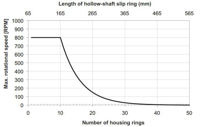
Slip Rings rotational speeds
The maximum rotational speed depends on the mounting position and on the number of channels (see fig.). For higher rotational speeds, please contact the manufacturer.
Slip rings are to be mounted by the customer so as to prevent them from oscillating and to ensure optimal rotation. The setscrews must be tightened evenly.
Unless otherwise specified, the shaft receiving the slip ring should have a h7 fit. Whenever possible, always tighten the opposite screws consecutively and evenly. In addition, at least 1/3 of the whole slip ring length should be in contact with the shaft.
Slip Rings Safety-Trans-Design
Two-chamber system for simultaneous power and signal transmission. The power and the signal area are separated by a special labyrinth seal. This allows minimizing a possible contamination of the signal contacts.
Software EzControl
ÃÂâÃÂ?ÃÂâ User-friendly programming software for counter types 716/717 and process indicators 55x
ÃÂâÃÂ?ÃÂâ Upload and download functions
ÃÂâÃÂ?ÃÂâ Monitor and terminal program for simple diagnostics
ÃÂâÃÂ?ÃÂâ Online display of measured values in the monitor program
ÃÂâÃÂ?ÃÂâ Multilingual
ÃÂâÃÂ?ÃÂâ Free download from our website
ÃÂâÃÂ?ÃÂâ Complete sets available with cable/plug-in power pack
ÃÂâÃÂ?ÃÂâ Upload and download functions
ÃÂâÃÂ?ÃÂâ Monitor and terminal program for simple diagnostics
ÃÂâÃÂ?ÃÂâ Online display of measured values in the monitor program
ÃÂâÃÂ?ÃÂâ Multilingual
ÃÂâÃÂ?ÃÂâ Free download from our website
ÃÂâÃÂ?ÃÂâ Complete sets available with cable/plug-in power pack
Software OS2
ÃÂâÃÂ?ÃÂâ User-friendly programming software for displays 570, 571 and 572 with serial interface
ÃÂâÃÂ?ÃÂâ Upload and download functions
ÃÂâÃÂ?ÃÂâ Monitor and terminal program for simple diagnostics
ÃÂâÃÂ?ÃÂâ Online display of measured values in the monitor program
ÃÂâÃÂ?ÃÂâ Free download from our website
ÃÂâÃÂ?ÃÂâ Upload and download functions
ÃÂâÃÂ?ÃÂâ Monitor and terminal program for simple diagnostics
ÃÂâÃÂ?ÃÂâ Online display of measured values in the monitor program
ÃÂâÃÂ?ÃÂâ Free download from our website
Spark quenching
If the pulse contact is within the DC circuit of the counter, spark quenching is necessary in order to avoid any contact disturbance from the inductive breaking voltage.
Unfortunately, however, a more or less strong dropout delay is produced by the spark quenching and it should be checked in any case whether this will cause disturbance.
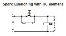
This spark quenching produces practically no disturbing dropout delay and is, therefore most suitable for all count speeds. It should preferably be used at very high count speeds. In general the RC element is located in parallel with the contact in order to produce high frequency interference suppression at the same time. However, it can also be connected in parallel with the coil.
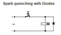
Considerable dropout delay, therefore only suitable for low count speeds up to 10 cps. Particular attention should be paid to the correct polarity on connecting. The small fitting size is an advantage: e.g. this type of spark quenching can be used for resetting coils.
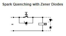
Low dropout delay, therefore suitable for higher count speeds because the diode only passes the inductive breaking current when the Zener voltage is achieved. It is also suitable for the protection of transistor circuits, where correct polarity must be observed.
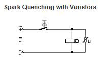
Varistors are voltage dependent resistors whose resistance decreases inertialessly and exponentially with rising voltage. They are therefore, suitable for spark quenching, the varistor ideally being connected in parallel with the coil. It is rated for the current to be approx. 1/10 of the coil current at nominal voltage.
Subtracting
The counter starts from the preset value or from a separate setpoint and counts down to zero, at which an output signal is triggered.
The counter is then reset to the preset value. The value displayed corresponds to the difference between the preset value and the count value.
Symmetrically capped Gray Code (Gray-Excess)
If a particular section of the complete Gray Code is extracted, this results in the so-called Gray Excess Code. This permits even-numbered divisions, such as 360, 720, 1000, and 1440.
Synchronous Serial Interface (SSI)
Compared to the parallel interface, the SSI interface needs less components and the EMC-characteristics are much better. In addition less lines are needed for transmission and the possible cable length is much longer.
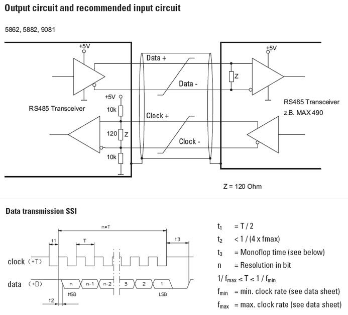
After the last positive-going clock-pulse edge the data line will remain for the duration of the monoflop time t3 at a low level, until the encoder is ready for a new data word. The clock line must stay high for at least as long, and then can begin a new read-out sequence again with the next falling edge.
Please note: Only for type 5850, 5870, 5862, 5882 and 9081
The updating of the data occurs synchronously with the read-out cycle. So, the data are as up-to-date as the interval time between two read-outs. A periodic read-out of the encoder in the application is therefore recommended, using appropriately short cycle times, so that current position values are constantly maintained. It is not possible to read out the same data word several times. Monoflop time of the encoder: t3 = max. 40 ÃÂ?ÃÂõs.
Only for the new Sendix Absolute encoders:
The updating of the data occurs immediately with the first falling edge of the clock signal. The data are thus always up-to-date. If a repeated read-out of the same data word is desired, then a new clock sequence must be started within the time interval t3. If the clock sequence is terminated before the necessary number of clock pulses, needed for a complete readout of the data word, has been transmitted, then after a further time interval t3 the data line will go high again and signal that the last read-out sequence has been aborted. It will also indicate that it is ready for a new data word to be sent. Monoflop time of the encoder: t3 = see data sheet.
The updating of the data occurs immediately with the first falling edge of the clock signal. The data are thus always up-to-date. If a repeated read-out of the same data word is desired, then a new clock sequence must be started within the time interval t3. If the clock sequence is terminated before the necessary number of clock pulses, needed for a complete readout of the data word, has been transmitted, then after a further time interval t3 the data line will go high again and signal that the last read-out sequence has been aborted. It will also indicate that it is ready for a new data word to be sent. Monoflop time of the encoder: t3 = see data sheet.
Tachometer
Tachometers measure pulses per unit of time, typically pulses per second with frequency measurements or pulses per minute with rotary speed measurement or production quantities and volumes. Two different measurement principles are used: time-interval measurement, where the time between 2 pulses is measured, or gate time (time base), where the number of pulses within a certain time window is measured. The latest models use a mix of both principles, which offers a fast reaction time coupled with the greatest possible accuracy. Devices with limit values can be used for monitoring rotary speed or rate of production.
Temperature compensation
This circuit ensures that the signal will remain the same over the whole working temperature range.
Benefit: The positioning accuracy of a machine will not be affected by temperature changes.
Temperature measuring range
The diagram below shows an overview of the temperature range of the various sensors.
Advice:
ÃÂâÃÂ?ÃÂ? for Pt100 resistance sensors adhere to DIN IEC 751
ÃÂâÃÂ?ÃÂ? for Ni100 resistance sensors adhere to DIN 43760
ÃÂâÃÂ?ÃÂ? for thermocouple sensors adhere to DIN IEC 584
ÃÂâÃÂ?ÃÂ? for Pt100 resistance sensors adhere to DIN IEC 751
ÃÂâÃÂ?ÃÂ? for Ni100 resistance sensors adhere to DIN 43760
ÃÂâÃÂ?ÃÂ? for thermocouple sensors adhere to DIN IEC 584
J: (Fe-CuNi)
These thermocouples are very common, economic and deliver a high thermoelectric voltage. Disadvantage: danger of corrosion. Iron becomes brittle with sulphurous gases.
These thermocouples are very common, economic and deliver a high thermoelectric voltage. Disadvantage: danger of corrosion. Iron becomes brittle with sulphurous gases.
K: (Ni-CrNi)
These thermocouples are very common, demonstrate excellent long-term stability but only have a low thermoelectric voltage.
These thermocouples are very common, demonstrate excellent long-term stability but only have a low thermoelectric voltage.
N: (NiCrSi-NiSi)
These thermocouples are not common, since they appeared only recently on the market. They can be used for very high temperatures and can replace elements out of noble metal.
These thermocouples are not common, since they appeared only recently on the market. They can be used for very high temperatures and can replace elements out of noble metal.
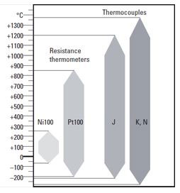
Temperature measuring with 2, 3 or 4 wire circuits
Unlike thermocouples, which deliver a voltage, a resistance does not deliver any signal by itself. This means that it requires external energy from an electrical measuring circuit. This power source is generally a constant current source.
With the 2 wire circuit, the measuring resistance is connected to the measuring device by means of two wires. The conductors are connected serially with the measuring resistance and lead to a higher total resistance, and thus to a measuring error.
With the 3 wire circuit, an additional wire is connected to the resistance, resulting in two measuring circuits. The resistance of the conductors is compensated for by means of internal circuits, provided all three conductors are identical.
With the 4 wire circuit, the resistance of all conductors is compensated for, even if they have different lengths.
Thermocouple sensors
Temperature measurement with thermocouple sensors uses the thermoelectric effect. Thermocouples consist of two wires, soldered together. The wires are made of different metals.
The thermoelectric voltage appearing at the soldering point is measured, amplified and displayed.
Time meter
Time meters (timers) measure the time in the unit of time, for which the device is laid out.
With electromechanical meters, this time is displayed in hours with one or two decimal places. With the electronic meters, the time base is programmable in hours, minutes or seconds and the resolution is determined by the decimal point.
Here the smallest possible resolution is milliseconds when operating in the short time meter mode (stop watch function). A time base of hours, minutes and seconds can also be programmed.
The time counting starts when the supply voltage is applied to the meter, or is controlled by means of pulses using either the time-interval measuring principle or the pulse width (gate time) principle, with one or two separate inputs.
Totaliser
The devices equipped with the integration function (totaliser) can calculate the integral, that is to say ÃÂâÃÂ?ÃÂ?totalizeÃÂâÃÂ?ÃÂàthe analogue signal, using any period of time.
A typical field of application is flow measurement. In this case, an analogue sensor measures the flow quantity per time unit in a pipe and displays the momentary flow value (e.g. litres per minute). The integration function (totaliser) calculates, from this constantly fluctuating quantity, a ÃÂâÃÂ?ÃÂ?totalÃÂâÃÂ?ÃÂÃÂ, that is to say it defines the absolute quantity that has flowed through the pipe (e.g. in litres).
Versions with coil
Max. possible frequency depends on the type of coil used:
Coil type = Max. frequency
--------------------------
05 = 8 Hz for DC
0 = 10 Hz for DC
1 = 25 Hz for DC
a0 = 10 Hz for AC
a = 18 Hz for AC
--------------------------
05 = 8 Hz for DC
0 = 10 Hz for DC
1 = 25 Hz for DC
a0 = 10 Hz for AC
a = 18 Hz for AC
Working temperature
Is defined as the environmental temperature, in which the encoder will produce the signals defined in the data sheets.
Zero signal
The zero signal is emitted once per revolution, it can be used e.g. as a reference signal during the first revolution after power.
12th Dec 2022