Contrinex Glossary of Terms
Contrinex 12th Dec 2022
Contrinex Glossary of Terms
ADJUSTMENT (POTENTIOMETER)
The sensitivity is adjusted by means of the built-in single or multi-turn potentiometer (if provided). Turning it clockwise increases the sensitivity. Multi-turn potentiometers cannot be turned over their end position (no stops).
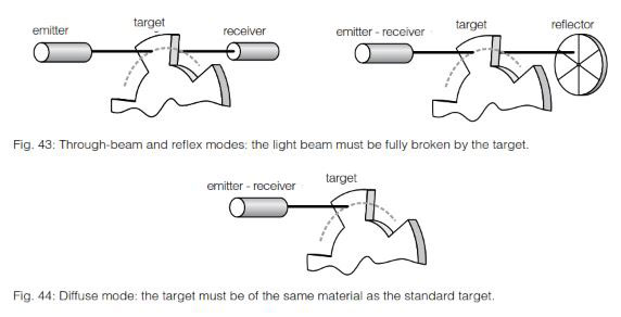
THROUGH-BEAM SENSORS / REFLEX SENSORS
The potentiometer is normally set to the maximum sensitivity (turned clockwise). This provides the maximum system reserve (excess-gain) signal.
DIFFUSE SENSORS
Set the sensitivity so that the target is reliably detected; for reliable operation, the green LED should light up, or the yellow LED should not flash (series 1040/1050/0507). On removing the object, if the output remains ON (detection of the background), the sensitivity must be reduced slightly.
DIFFUSE SENSORS WITH BACKGROUND SUPPRESSION
The setup must ensure that the target is clearly identified, and any background excluded. The target should first be positioned at the maximum foreseen distance from the emitter, and the potentiometer adjusted so that the output just switches. The target is then removed and the potentiometer adjusted so that the background just causes the output to switch. Finally, the potentiometer is set to half way between the two previous readings. Where there is no background, the potentiometer should be set to the maximum distance.
ALIGNMENT
THROUGH-BEAM SENSORS
First place the receiver and fix it in its final position. Then align the emitter accurately onto the receiver.
REFLEX SENSORS
First place the reflector as required and fix it firmly in position. Fit the reflex sensor with the optical axis aligned on the reflector so that it switches reliably. Test with target. Reduce sensitivity if necessary.
DIFFUSE SENSORS
Align the unitÃÂâÃÂ?ÃÂ?s optical axis with the target so that switching occurs reliably. Check that enough system reserves (excess gain) are available, i.e. the green LED must light up (series 1120, 1180, 1180W, 3030, 3031, 3060, 4040, 4050 and C23). Finally, fix the device firmly.
DIFFUSE SENSORS WITH BACKGROUND SUPPRESSION
Line up the beam on the center of the target, before fixing the device firmly.
AMBIENT LIGHT LIMIT
Ambient light is that which is produced by external light sources. The illumination intensity is measured on the light incidence surface. The sensors are basically insensi- tive to ambient light due to the use of modulated light. There is nevertheless an upper limit for the intensity of any external light and this is referred to as the ambient light limit. It is given for sunlight (unmodulated light) and halogen lamps (light modulated at twice the mains frequency). Reliable operation of the units is no longer possible at light intensities above the relevant ambient light limit.
AMBIENT TEMPERATURE
The specified ambient temperature range must not be exceeded in order to avoid damaging the sensor and rendering its performance unreliable.
ANALOG OUTPUT
Devices with analog output deliver an analog output signal approximately proportional to the target distance. For most models, voltage and current outputs are available simultaneously.
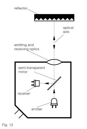
AUTOCOLLIMATION
Photoelectric sensors using the autocol- limation principle are characterized by the fact that the optical axes of the emitting and receiving channels are identical. This is possible with light from one of the channels being deflected by means of a semi-transparent mirror (Fig. 13). This principle completely eliminates the interfering blind zone often found in the proximity of the sensor, which is of special advantage when using reflex sensors.
BACKGROUND SUPPRESSION
The light pulse from the emitting diode leaves the optical system as a focused, almost parallel, light beam. On meeting an object in its path, part of the beam is diffusely reflected, and in turn, part of this reflected light falls on the PSD (Position- Sensitive Device) housed in the same sensor (Fig. 14).
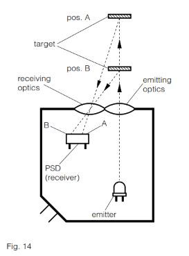
Depending on the distance of the target from the device, the light falls on a particu- lar spot of the PSD, and a corresponding reception signal is emitted, indicating that an object is present at a certain distance from the device. The analyzing circuit compares the signal received with the preset operating distance (adjusted by means of the built-in potentiometer), and, if the distance of the object is less than, or equal to, the preset operating distance, the output is switched. Contrary to an energetic diffuse sensor, the operating distance depends only to a very small extent on the targetÃÂâÃÂ?ÃÂ?s size or color, or on the nature of its surface. The object can therefore be easily discerned, even against a light background.
CAPACITANCE
The maximum switchable capacitance is the greatest permissible total capacitance at the deviceÃÂâÃÂ?ÃÂ?s output so that reliable switching is still guaranteed. Contributing to this total capacitance in particular are the lead capacitance (approx. 100 ... 200 pF per m) and the loadÃÂâÃÂ?ÃÂ?s input capacitance. The value is given in the individual data sheets. These can be ordered from our sales offices.
CE MARK
All sensors in this catalog meet the requirements of European standards EN 60947-1 and EN 60947-5-2, and therefore correspond to EMC directive 2004/108/EC, as well as low-voltage directive 2006/95/EC. Consequently, they are labeled with the CE mark.
However, this mark is neither a quality seal, nor an official test label certified by any authority. By applying the CE mark, the manufacturer confirms (under his own responsibility) that the protective requirements for the product meet the applicable EU directives, and consequently that the corresponding EU standards have been complied with. The CE mark enables the free importation of goods into the EU, as well as their free circulation within the EU.
CHANGEOVER
Devices with changeover outputs provide one output for the light-ON or NO signal, and another for the dark-ON or NC signal. Both functions are available simultaneously for maximum connection flexibility to the control unit. Moreover, logical connections may be implemented without using series connection. Connecting both outputs to the control unit allows additional security monitoring.
CLASSICS FAMILY
The Classics family (600 series) is one of three inductive sensing technologies offered by Contrinex. Classics family sensors rely on conventional inductive oscillator and coil technology (see page 20).
Sensors are sized from ÃÂ?ÃÂ? 3 up to M30 and C44 (40 mm x 40 mm). PNP, NPN and 2-wire AC/DC output configurations are available, combined with sensing distances between 0.6 mm and 40 mm.
The Classics technology family includes devices from the following ranges: Basic, Miniature, 2-wire, Extra pressure, Extra temperature, High temperature and Washdown.
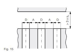
CLEARANCE
Inductive sensors must not mutually influence each other. For this reason, a minimum distance A between devices of diameter D must be observed (Fig. 15).
EXTRA DISTANCE (SERIES 500, 520*)
th,td {border:1px solid black;border-collapse:collapse;padding:7px;}
| Size D | (quasi)-embed. A (mm) | non-emb. A (mm) |
|---|---|---|
| ÃÂ?ÃÂ? 4 | 6 (embeddable) | --- |
| M5 | 5 (embeddable) | --- |
| ÃÂ?ÃÂ? 6.5 | 9.5 | --- |
| M8 | 8/*16 | 20 |
| C8 | 8 | --- |
| M12 | 18/*34 | 30 |
| M18 | 26 | 60 |
| M30 | 50 | 120 |
CLASSICS (SERIES 600, 620*)
th,td {border:1px solid black;border-collapse:collapse;padding:7px;}
| Size D | embeddable A (mm) | non-emb. A (mm) |
|---|---|---|
| ÃÂ?ÃÂ? 3 | 0/*2 | --- |
| M4 | 0/*1 | --- |
| ÃÂ?ÃÂ? 4 | 0/*1 | --- |
| M5 | 0/*1 | --- |
| C5 | 0/*1 | --- |
| ÃÂ?ÃÂ? 6.5 | 3/*3.5 | ---/*15.5 |
| M8 | 2/*4 | 10/*14 |
| C8 | 2/*2 | --- |
| M12 | 4/*12 | 28/*33 |
| M18 | 7/*22 | 32 |
| M30 | 10 | 50 |
| C44 | 35 | 120 |
FULL INOX (SERIES 700)
th,td {border:1px solid black;border-collapse:collapse;padding:7px;}
| Size D | embeddable A (mm) | non-emb. A (mm) |
|---|---|---|
| M8 | 14 | 52 |
| M12 | 38 | 108 |
| M18 | 42 | 182 |
| M30 | 80 | 270 |
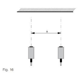
Photoelectric sensors must not mutually influence each other. For this reason, a minimum distance "a" between them has to be respected, which depends strongly on the model used and the actual sensitivity setting. The following values should therefore be considered as rough guidelines only. The values given are for maximum sensitivity.
DIFFUSE SENSORS WITH BACKGROUND SUPPRESSION
th,td {border:1px solid black;border-collapse:collapse;padding:7px;}
| Series | distance a (mm) |
|---|---|
| Series 1180/1180W | 50 |
| Series 3130 | 50 |
| Series 3131 | 50 |
| Series 4050 | 100 |
DIFFUSE SENSORS (FIG. 16)
th,td {border:1px solid black;border-collapse:collapse;padding:7px;}
| Series | distance a (mm) |
|---|---|
| Series 1040/50 | 50 |
| Series 1040/50...505 | 15 |
| Series 1040/50...506 | 30 |
| Series 1120 | 150 |
| Series 1180/1180W | 500 |
| Series 3030 | 500 |
| Series 3031 | 250 |
| Series 4050 | 150 |
REFLEX SENSORS (FIG. 17)
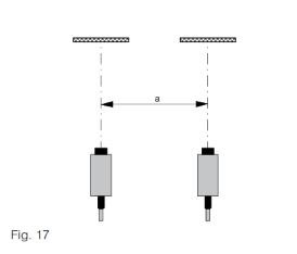
th,td {border:1px solid black;border-collapse:collapse;padding:7px;}
| Series | distance a (mm) |
|---|---|
| Series 1120 | 150 |
| Series 1180/1180W | 250 |
| Series 3030 | 500 |
| Series 3031 | 250 |
| Series 4050 | 200 |
THROUGH-BEAM SENSORS (FIG. 18)
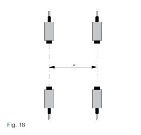
th,td {border:1px solid black;border-collapse:collapse;padding:7px;}
| Series | distance a (mm) |
|---|---|
| Series 1040/50 | 50 |
| Series 1120 | 150 |
| Series 1180/1180W | 250 |
| Series 3030 | 500 |
| Series 3031 | 250 |
| Series 4050 | 500 |
FIBER-OPTIC AMPLIFIERS
The value "a" depends strongly on the specific type of fiber used. General recom- mendations are therefore not possible.
CONDET TECHNOLOGY
An innovative technology for producing inductive sensors. Contrary to conventional technology, in which a high-frequency magnetic field is generated in front of the sensing face, here the coil is triggered by an alternating polarity pulsed current. This technology is used in the Full Inox family (700 series) (see also page 21).
It permits:
? generally long operating distances
? long operating distances also on non- ferrous metals, such as aluminum, brass, copper, etc.
? one-piece stainless steel housing
(sensing face included)
? long operating distances also on non- ferrous metals, such as aluminum, brass, copper, etc.
? one-piece stainless steel housing
(sensing face included)
CONDIST TECHNOLOGY
Developed by Contrinex, this innovative technology makes use of a high-perfor- mance oscillator for inductive sensors. Operating distances from 2.2 to 4 times the standard values are possible thanks to excellent temperature and voltage stabil- ity. Devices of the Extra distance family (500 and 520 series) work with such an oscillator (see also page 20).
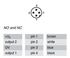
CONNECTORS
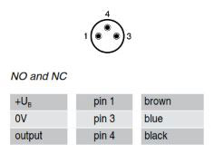
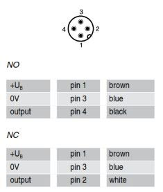
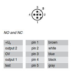
PIN ASSIGNMENT SIZE S8:
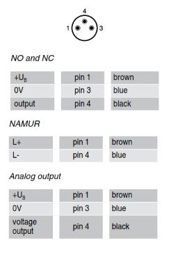
Detailed data sheets for these products can be found on the Contrinex website:
PIN ASSIGNMENT SIZE S12:
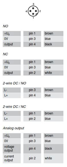
PIN ASSIGNMENT SIZE 1/2":
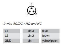
PIN ASSIGNMENT SIZE S8 3 POLE:
PIN ASSIGNMENT SIZE S12 3 POLE:
PIN ASSIGNMENT SIZE S12 5 POLE:
PIN ASSIGNMENT S8 4 POLE:
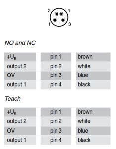
PIN ASSIGNMENT S12 4 POLE:
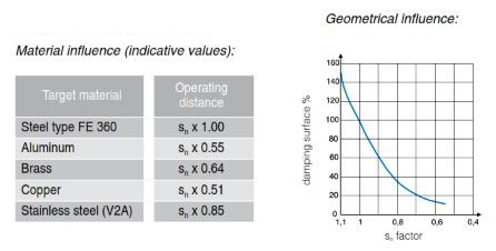
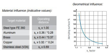
CORRECTION FACTORS
The specified operating distance s of inductive sensors refers to exactly defined measuring conditions (see OPERATING DISTANCE).
Other arrangements generally result in a reduction of the operating distance. The fol- lowing data are to be considered as guidelines only; according to size and version, there can be wide variations. Exact values are given in the individual data sheets. These can be ordered directly from our sales offices.
CLASSICS (SERIES 600 / 620)
When using foils, an increase in the usable operating distance can be expected.
EXTRA DISTANCE (SERIES 500 / 520*)
When using foils, an increase in the usable operating distance can be expected.
FULL INOX (SERIES 700)
Material influence (indicative values):
th,td {border:1px solid black;border-collapse:collapse;padding:7px;}
| Target material | Operating distance |
|---|---|
| Steel type FE 360 | Sn x 1.0 |
| Aluminum | Sn x 1.0 |
| Brass | Sn x 1.3 |
| Copper | Sn x 0.8 |
| Stainless Steel (1 mm thick) | Sn x 0.5 |
| Stainless Steel (2 mm thick) | Sn x 0.9 |
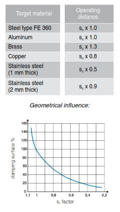
When using foils, a decrease in the usable operating distance can be expected.
Test card (Kodak paper, white) 100%
Paper, white 80%
PVC, gray 57%
Newspaper, printed 60%
Wood, lightly colored 73%
Cork 65%
Plastic, white 70%
Plastic, black 22%
Neoprene, black 20%
Automobile tires 15%
Aluminum sheet, untreated 200%
Aluminum sheet, black anodized 150%
Aluminum sheet, matt (brushed finish) 120%
Stainless steel, polished 230%
The specified sensing ranges of energetic diffuse sensors are achieved using standard matt white paper of the specified dimensions as the target surface. For other target surface materials, the correction factors listed here apply (these are guideline values only).
DARK-ON
The "dark-ON" function means that the relevant output is switched (carrying current) when no light is reaching the receiver.
DEGREES of PROTECTION
The IP degrees of protection are defined in DIN 40050 / IEC 60529. The meaning of the first numeral is:
6 The housing provides complete protection against contact with electrically con- ducting or moving parts, and full protection against dust penetration.
and the second numeral:
4 Protection against water splashes: water splashed against the housing from any direction must have no harmful effect. Test conditions: spraying with oscillating tube or spray nozzle; water pressure 1 bar; delivery rate 10 l/min ÃÂ?ÃÂñ 5%; duration 5 minutes.
5 Protection against water jets: water projected by a nozzle from any direction under specified conditions must have no harmful effect. Test conditions: nozzle with 6.3 mm diameter; delivery rate 12.5 l/min ÃÂ?ÃÂñ 5%; distance 3 m; duration 3 minutes.
7 Protection against water when device is immersed in water under specified pres- sure and time conditions. Water must not penetrate in damaging quantities. Test conditions: immersion depth in water 1 m; duration 30 minutes.
8 Protection against water when device is immersed in water indefinitely under specified pressure conditions. Water must not penetrate in damaging quantities. Test conditions used by Contrinex: immersion depth in water 5 m; duration ? 1 month.
9K Protection against water which, if directed against the housing from any direction and under considerably increased pressure, must have no harmful effect. Test conditions: sensor mounted on table turning at 5 ÃÂ?ÃÂñ 1 rpm; spraying with flat nozzle; delivery rate 14 - 16 l/min; distance 100 - 150 mm; angles 0ÃÂ?ÃÂð, 30ÃÂ?ÃÂð, 60ÃÂ?ÃÂð and 90ÃÂ?ÃÂð; temperature 80 ÃÂ?ÃÂñ 5ÃÂ?ÃÂðC (176 ÃÂ?ÃÂñ 41of); pressure 8,000 - 10,000 kPa (80 - 100 bar / 1160.8 - 1451 psi); duration 30 sec per position.
Devices with degree of protection IP 67 are thus not intended for prolonged operation in water, or in prolonged humid conditions. Tolerance to liquids other than water must be examined from case to case.
EMBEDDABLE MOUNTING
See MOUNTING.
EMC
The EMC (Electromagnetic Compatibility) resistance of the devices satisfies the highest demands. For exact values, please refer to the data sheets. All devices comply with the EU directive no. 2004/108/EC. In addition, they undergo severe field testing.
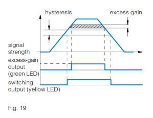
EXCESS-GAIN INDICATION (SYSTEM RESERVE INDICATION)
The excess-gain indication circuit detects the excess radiation power which falls on the light incidence surface and is proc- essed by the light receiver. The excess gain can decrease in time due to dirt, a change in the targetÃÂâÃÂ?ÃÂ?s reflection factor, and aging of the emitter diode, so that reliable operation can no longer be guaranteed. Some devices are therefore equipped with a second LED (green), which lights up when less than approximately 80% of the available operating distance is used. Models with an excess-gain output make the excess-gain signal available to the user for further processing. Thus, operating condi- tions which are no longer reliable can be recognized in time.
EXTRA DISTANCE FAMILY
The Extra Distance family (series 500/520) is one of three inductive sensing tech- nologies offered by Contrinex. Extra Distance family sensors rely on conventional inductive oscillator and coil technology, but with a completely different signal evaluation circuit for better stability and therefore long operating distances. The most important contribution to this comes from the Contrinex Condist oscillator (see pages 20-21). Sensors are sized from ÃÂ?ÃÂ? 4 to M30, with long operating distances up to 40 mm. The Extra Distance technology family includes devices from the Basic, Miniature, Extra pressure, High pressure and Analog output ranges.
FULL INOX FAMILY
The Full Inox family (series 700) is one of three inductive sensing technologies of- fered by Contrinex. Full Inox family sensors rely on ContrinexÃÂâÃÂ?ÃÂ?s patented Condet technology (see page 21).
Full Inox sensors have a one-piece, stainless steel housing and are exceptionally robust and chemically resistant. They are not only the most durable inductive sensors on the market, but also offer long operating distances on any conductive metal.
Sensors are sized from ÃÂ?ÃÂ? 4 to M30 and cuboid variant of 20 x 32 x 8 mm, with long operating distances up to 40 mm and protection class IP 67 and IP 69K.
The Full Inox technology family includes devices from the Basic, Miniature, Extreme, High pressure, Washdown, Weld-immune, Chip-immune, Double-sheet and Maritime ranges.
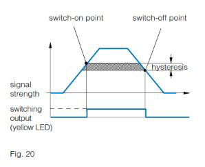
HYSTERESIS
Hysteresis (differential travel) causes a defined switching behavior of the device (Fig. 20). The sensing range always refers to the switch-on point. Distance hysteresis is only useful for the diffuse sensor model and its related fiber version.
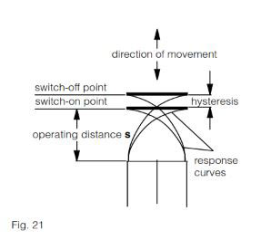
Hysteresis (differential travel) causes a defined switching behavior of the device (Fig. 21). The operating distance always refers to the switch-on point. Namur devices and those with analog output have continuous transmission behavior, i.e. there is no hysteresis.
INDUCTION PROTECTION
When inductive loads are switched off, the output voltage, without a protective circuit, would increase to a high value, which could destroy the output transistor. Contrinex sensors therefore contain a Zener diode at the output to limit the switch-off voltage to a safe value (3-wire types). When connecting an inductive load with a current >100 mA and simultaneously a switching frequency >10 Hz, the mounting of a free-wheeling diode directly to the load is recommended (due to the leakage power in the built-in Zener diode).
INSTALLATION
Photoelectric sensors can be easily and reliably installed in any position, using the mounting accessories supplied with most devices. The installation position should preferably protect the units against dirt and other contamination.
For inductive sensors, see MOUNTING.
INSULATION VOLTAGE
The devices in this catalog are designed for an insulation voltage (between connect- ing leads and housing) of 75 VDC / 50 VAC (for supply voltages up to 75 VDC / 50 VAC) or 300 VDC / 250 VAC (for supply voltages between 75 VDC / 50 VAC and 300 VDC / 250 VAC).
IP 64 / IP 65 / IP 67 / IP 68 / IP 69K
Refer to DEGREES of PROTECTION.
IR LIGHT
IR is the abbreviation of "Infra-Red". This refers to any electromagnetic radiation with a wavelength exceeding that of normal visible light, which is approx. 380 to 780 nm. Wavelengths of approx. 780 to 1500 nm are typically used. IR light cannot be used with synthetic fibers, due to high at- tenuation. Instead, visible red light is used. As the usual polarization filters cannot be used in the IR range, visible red light is also used for reflex sensors.
LEAD LENGTHS
For the sensor, long leads mean:
? a capacitive load at the output (see CAPACITANCE)
? increased influence of interference signals
? increased influence of interference signals
Even under favorable conditions, lead lengths should not exceed 300 m.
LEADS
The standard built-in leads are not suit- able for repeated bending stresses. In such cases, high-flexibility PUR cables (special executions) or connectors with corresponding connecting cables (see pages 441-449) must be used.
LEAKAGE CURRENT
Leakage current is the current that flows through the output transistor and thereby through the load when the output is OFF (to be taken into account particularly where switches are connected in parallel).
LED
Most of the inductive devices in this catalog are equipped with a built-in yellow light- emitting diode (LED). It indicates the switching state: output activated = yellow LED on.
All photoelectric sensors have one or two Light Emitting Diodes (LEDs) built in. The yellow LED lights up when the output is switched (for switches with 2 outputs: the light-ON output). During a short-circuit or overload, the yellow LED does not operate. The green LED (if provided) lights up when enough system reserves (excess gain) for reliable operation are available, i.e. when an object is present in the reliable sensing area (diffuse sensors), or when enough light from the uninterrupted beam reaches the receiver (reflex and through-beam sensors).
LIGHT-ON
Light-ON means that the relevant output is switched (carrying current) when light is reaching the receiver.
LOAD RESISTANCE
From the selected supply voltage UB and the specified maximum output current of the sensor, the lowest permissible load resistance for trouble-free operation can be calculated. Example: With a voltage of 24 V and a specified maximum permissible output current of 200 mA, the minimum load resistance is 120 ohm; at 15 V, it is 75 ohm.
MAGNETIC FIELDS
Strong fields can saturate the ferrite core of inductive sensors, thereby increasing the operating distance, or even provoking false switching. However, no lasting dam- age is caused. High-frequency fields of several kHz (700 series), or several hundred kHz (other series), may seriously interfere with the switch functioning, since the oscillator frequency of the devices lies in this range. If difficulties with interfering magnetic fields are encountered, shielding is recommended.
MODULATED LIGHT
The photoelectric sensors listed in this catalog operate with modulated light, i.e. the light emitter is switched on only for a short period and remains switched off for much longer (ratio approx. 1:25). In dif- fuse and reflex sensors, the receiver is only active during the light pulse, and is disabled during the pulse gap. Operation with modulated light provides the following advantages:
? The devices are largely insensitive to ambient light
? Longer sensing ranges are possible
? Heat generation is reduced, which pro- longs the operating life of the emitting diodes
MODULATION FREQUENCY
The photoelectric devices in this catalog are operated with modulated light, which makes them largely insensitive to ambient light. The modulation frequency f(cy) is in the range of several kHz. If a device is operated in the proximity of another device with the same modulation frequency, interference can occur.
MOUNTING
For photoelectric sensors, see INSTALLATION.
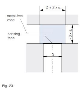
EMBEDDABLE SENSORS
Embeddable sensors may be flush mounted in all metals. For trouble-free operation, a free zone according to Fig. 23 should be observed.
QUASI-EMBEDDABLE SENSORS
When installing quasi-embeddable Extra Distance sensors (500 and 520 series) in conductive materials (metals), the devices must protrude by a distance X, accord- ing to Fig. 24. Further, a free zone of 3 x sn must be observed. Flush mounting in non-conducting materials is permitted.
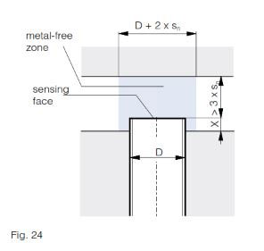
Mounting in steel and in non-ferrous metals:
Housing size D X (mm)
ÃÂ?ÃÂ? 6.5 1
C8 1
M12 2
M18 4
M30 6
Mounting in stainless steel:
Housing size D X (mm)
ÃÂ?ÃÂ? 6.5 0.0
C8 0.0
M12 1.0
M18 1.5
M30 2.0
NON-EMBEDDABLE SENSORS
When mounting non-embeddable sensors in conducting materials (metals), minimum distances to the conducting material must be maintained according to Fig. 25. Flush mounting in non-conducting materials is permitted.
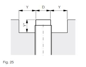
Housing size D Y (mm)
M8 8
M12 12
M18 22
M30 40
C44 60 / *40
NC
The output is open when the switch is not activated. It is closed when the switch is activated.
NO
The output is open when the switch is not activated. it is closed when the switch is activated.
NO-LOAD SUPPLY CURRENT
No-load supply current is understood as the inherent consumption of the sensor for operating the LED, amplifier, etc., in the non-activated state. It does not include the current flowing through the load.
NON-EMBEDDABLE MOUNTING
See MOUNTING.
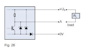
NPN CONFIGURATION
The output device contains an NPN transis- tor, which switches the load towards zero voltage. The load is connected between the output terminal and the positive supply voltage +UB (Fig. 26).
OIL RESISTANCE
Long-term contact with any oils may af- fect plastics and weaken their resistance. However, inductive Full Inox sensors (series 700), as well as the sealed (series E) and high-pressure-resistant (series P) types can be used in oily environments without restriction. For all other types, this is not necessarily the case.
Thus, please observe the following:
Lubricating oils:
Generally cause no problems. Use versions with oil-resistant PUR cable (special executions).
Hydraulic oils, cutting oils:
These attack most plastics. In particular, PVC cables discolor and become brittle.
Measures:
? Wherever possible, avoid contact with these liquids, particularly at the sensing face.
? Use versions with oil-resistant PUR cable.
For photoelectric sensors, housing, optical unit, and cable should be considered separately:
Housing
The PBTP / polybutyleneterephthalate (Crastin) used for the housing is highly resist- ant to all conventional types of oil, in particular, to cutting and hydraulic oils, as well as drilling emulsions.
Optics
The windows are generally of glass (with the exception of series 4150 and 5050), and are therefore not affected. However, oil on the light in- and outputs changes their optical properties. The effects should be examined from case to case.
Cable
The PVC cable used as standard is not resistant to most types of oil, and becomes brittle in long-term use. The optional PUR cable should therefore be used in oily environments.
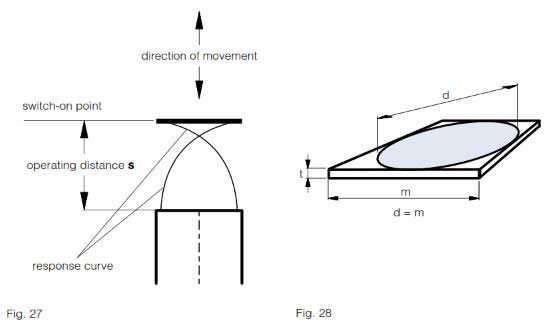
OPERATING DISTANCE
The operating distance of inductive sensors is the distance at which a target approach- ing the sensing face triggers a signal change. The operating distance is measured according to IEC 60947-5-2 / EN 60947-5-2, using a standard square target moving axially (Fig. 27). This target is made of steel, e.g. type FE 360 in accordance with ISO 630, with a smooth surface, square shape, and thickness of 1 mm (Fig. 28). The sides equal the diameter of the inscribed circle of the sensing face or three times the rated operating distance sn of the sensor, whichever is the greater.
Rated operating distance sn
This is the operating distance for which the sensor is designed. It can be found under "technical data".
Effective operating distance sr
The measured operating distance for a given switch according to IEC 60947-5-2 / EN 60947-5-2.
0.9 sn ? sr ? 1.1 sn
This means that the manufacturing tolerance must not exceed ÃÂ?ÃÂñ 10%.
Usable operating distance su
This distance takes into account expected additional deviations caused by temperature and supply voltage fluctuations within the specified range.
0.9 sr ? su ? 1.1 sr
The temperature and supply voltage ranges can be found under "technical data".
Assured operating distance sa
0 ? sa ? 0.81 sn
This operating distance is guaranteed by the manufacturer for all specified operating conditions. It is the basis for a safe design.
See SENSING RANGE.
OPTICAL FIBERS
An optical fiber can consist of a bundle of glass fibers, or one or more synthetic fibers. It is used to conduct light from one place to another, even around bends and curves. This is possible thanks to the pheno menon of total reflection. Total reflection always occurs when light coming from a material with a higher refractive index falls on an interface with a medium having a lower refractive index, in such a way that the critical angle required for total reflection is never reached.
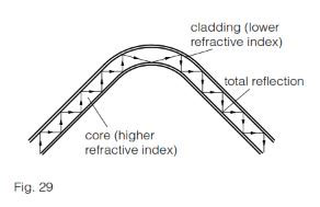
The fibers consist of a core (with a higher refractive index) and a cladding (with a lower refractive index). Due to total reflection, the light is reflected backwards and forwards in the core, and can thus go round bends and curves.
OUTPUT CURRENT
The devices are designed for a given maximum output current. If this current is ex- ceeded, even for only a short time, the overload protection trips. Incandescent lamps, capacitors, and other heavily capacitative loads (e.g. long leads) have a similar effect to overload (see also CAPACITANCE).
OUTPUT RESISTANCE
In order that the output voltage, even without external load, follows the switching state, Contrinex sensors contain a built-in output resistance (pull-up or pull-down resistor). For operation at high switching frequencies, an additional external load resistor must be added (to reduce the electrical time constant).
OVERVOLTAGE PROTECTION
For maximum operating reliability and ease of use, Contrinex sensors feature a built-in protection circuit against very short, non-periodic supply voltage peaks, which complies with the requirements of IEC 60947-5-2.
PARALLEL CONNECTION
Connecting sensors in parallel, in order to perform logic functions, is possible without any problem (Figs. 30 and 31).
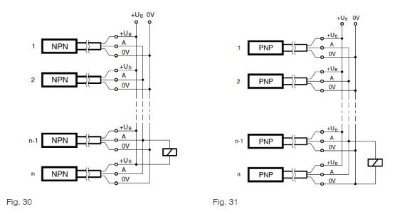
Please note:
? The no-load supply current increases.
? Leakage currents add up, so that, even when closed, an inadmissible voltage drop can occur at the output.
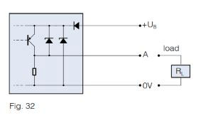
PNP CONFIGURATION
The output device contains a PNP transistor, which switches the load towards the positive supply voltage +UB. The load is connected between the output terminal and the negative supply voltage 0V (Fig. 32).
POLARITY REVERSAL PROTECTION
Virtually all sensors in this catalog are protected against any polarity reversal at all terminals.
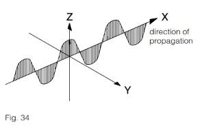
POLARIZATION FILTER
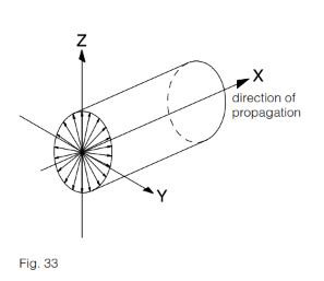
Natural light (including the light from the emitter diodes) is not polarized (Fig. 33). When light has passed through a polarizing filter however, only that part of the original light which oscillates in the filter polariza- tion direction is still present (Fig. 34). Polarization is retained after reflection by mirrored surfaces, only the direction of polarization may be altered. Diffuse reflection, on the other hand, destroys polarization. This difference can be used to suppress the disruptive effects caused by mirrored surfaces, by means of selection and configuration of suitable filters.
POWER-ON RESET
When switched on, the sensor output is activated for a short time due to physical reasons, even without the presence of a target in front of the sensing face. Sensors with power-on reset therefore include an additional circuit that closes the output for a short time during the switching-on phase, so suppressing an error signal (this function is also known as "switch-on pulse suppression").
POWER SUPPLY UNITS
Circuit recommendations for suitable power supply units are shown in Figs. 35 and 36.
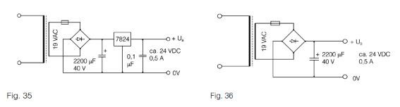
Please observe:
? Unsuitable power supply units are the most frequent reason for sensor problems!
? A transformer and rectifier are not sufficient; at least a smoothing capacitor is es- sential (due to the ripple content).
? Transformers with a 24 V output, rear-position rectifier and smoothing capacitor deliver a no-load voltage of well above 30 V. Consequently, devices with a maximum supply voltage of 30 V can be damaged.
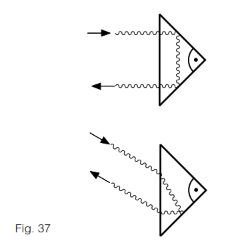
REFLECTORS
By means of built-in polarization filters, polarized reflex sensors are designed so that they respond only to the light reflected from special reflectors. These operate according to the principle of the 3-way mirror (Fig. 37). The choice of the correct reflector for a specific application is determined by the required operating distance and installation possibilities. The reflector must be installed perpendicularly to the optical axis (tolerance ÃÂ?ÃÂñ 15ÃÂ?ÃÂð).
REPEAT ACCURACY
Repeat accuracy (according to IEC 60947-5-2 / EN 60947-5-2) is understood to be the repeat accuracy of the effective operating distance sr over an 8-hour period at an ambient temperature of 23 ÃÂ?ÃÂñ 5ÃÂ?ÃÂðC (73.4 ÃÂ?ÃÂñ 41 degrees F) and with a specified supply voltage UB. The specified repeat accuracy refers to this definition. Successive measure- ments made immediately one after the other generally lead to much better repeat accuracy.
RESPONSE DIAGRAM
The specified values for the operating distance refer to an axial approach of the target. For staggered or lateral movements, type-specific response curves are valid. Two typical examples are shown below (Fig. 38 and Fig. 39):
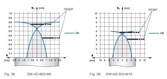
Depending on series, size, and mounting type (embeddable or non-embeddable), the response diagrams differ. Response diagrams for switch types not shown here are readily available from the corresponding individual data sheets. These can be ordered from our sales offices.
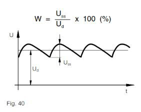
RIPPLE CONTENT
Too much ripple content causes undefined switching behavior. To remedy this, use a larger smoothing capacitor, or a stabilized power supply unit. The specified maximum supply voltage UB must not be exceeded, not even during Uss peaks.
SAFETY
The devices in this catalog have not been designed for safety-relevant use. In cases where the safety of people is dependent on their functioning, it is the user's responsibility to ensure that the relevant standards, in particular ISO 13849-1, and regulations are complied with. Contrinex assumes no liability for personal injury.
SENSING RANGE
The specified sensing range of photo- electric sensors is the maximum usable distance between the device and the standard target (diffuse sensors); between the device and the reference reflector (reflex sensors), and between the emitter and the receiver (through-beam sensors). The potentiometer must be set for maxi- mum sensitivity, or for diffuse sensors with background suppression, for maximum sensing range. Moreover, the specified reflector (reflex sensors) or standard target (diffuse sensors) must be used.
SERIES CONNECTION
The connection of sensors in series in order to achieve logic functions is possible, but not recommended. The same effect can be achieved by the parallel connection of sensors with NC function (instead of the series connection of models with NO function), or vice versa. However, please note that, as a result, the output signal is inverted.
SHOCK RESISTANCE
The sensors in this catalog are tested for resistance to a shock of 30 g (30 times gravitational acceleration) for a period of 11 ms, according to IEC 60068-2-27.
SHORT-CIRCUIT PROTECTION
The devices in this catalog feature built- in pulse protection against short-circuits and overloads, which alternately closes and opens the output when the maximum output current is exceeded, until the short-circuit is eliminated. Short-circuits between the output and the supply voltage terminals do not damage the sensor, and are allowed in permanence. The same applies to overloads. During short-circuits, the LEDs do not function.
SPHERICAL OPTICS
Spherical lenses are special versions of double convex lenses. They feature a short focal length and a good light incidence area. Fig. 41 shows such a design in sensor type LT#-1040/1050-30#-50# (see pages 229-235). For diffuse sensors, the sphere is cut in two to separate the reception from the emission channel.
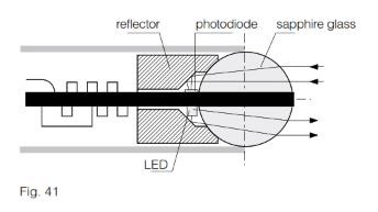
The emitter and receiver chips are mounted as closely as possible to the surface of the sphere and slightly off the optical axis (see Fig. 41). This causes the emitted beam to intersect the receiverÃÂâÃÂ?ÃÂ?s sensing range at a specific distance from the device, resulting in a relatively short sensing range, but a virtually cylindrical detection zone. A cylindrical detection zone is particularly useful in some applications, such as the detection of targets through narrow holes or gaps.
STANDARDS
The sensors in this catalog comply, either completely or to a great extent, with the following standards:
? IEC 60947-5-1, IEC 60947-5-2, EN 60947-5-1, EN 60947-5-2
? IEC 61000-4-1, 61000-4-2, 61000-4-3, 61000-4-4, DIN EN 55011, DIN EN 55081-2, DIN EN 50140
? IEC 60529 / DIN 40050
? IEC 60947-1 / EN 60947-1 / DIN VDE 0660, part 100, part 100 A3, part 200, part 208
? DIN EN 50008, 50010, 50025, 50026, 50032, 50036, 50037, 50038, 50040, 50044
SUPPLY VOLTAGE UB
The specified maximum supply voltages must not be exceeded. For maximum operating reliability and ease of use, Con- trinex sensors contain a built-in protection circuit against very short, non-periodic, supply voltage peaks, which complies with the requirements of IEC 60947-5-2. Operating voltages below the lower speci- fied limit, even for short periods, do not damage the switches, but impede their operation.
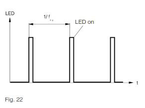
SWITCHING FREQUENCY
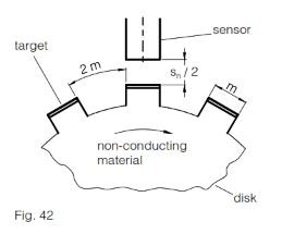
The maximum switching frequency of inductive sensors indicates the highest permissible number of pulses per second for a constant pulse/pause ratio of 1 : 2 at half the rated operating distance sn. Measurement is according to IEC 60947-5- 2 / EN 60947-5-2 (Fig. 42).
In the case of photoelectric sensors, the frequency of operating cycles (f) is determined from the formula:
f = 1 / (tON + tOFF)
where:
ton is the turn on time
toff is the turn off time
ton and toff are measured in accordance with IEC60947-5-2 2007 paragraph 8.5.3. (see also Turn-on/turn-off time, in this glossary).
TEACH-IN
Some devices have a teach-in capability instead of a potentiometer to adjust their sensing range, etc. Teach-in is achieved either directly by pressing a button or re- motely via IO-Link.
TEMPERATURE DRIFT
The set sensing ranges are subject to slight temperature influences. Due to built- in temperature compensation, this effect is much less important for devices of the 4040 series (approx. 0.1 % / ÃÂ?ÃÂðC) than for the other switches (approx. 0.3 %/ÃÂ?ÃÂðC). The sensing range, as a function of ambient temperature, follows approximately the curves shown in Fig. 45.
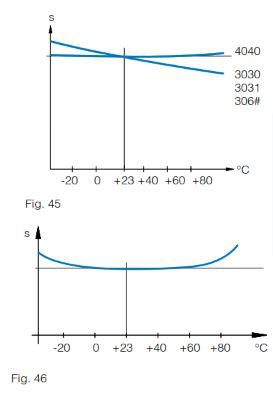
The specified operating distances refer to a nominal ambient temperature of 23ÃÂ?ÃÂðC (73.4of). The operating distance, as a function of ambient temperature, follows approximately the curve shown in Fig. 46.
The temperature of the target itself has practically no influence on the operating dis- tance. Within the permitted temperature range of, as a rule, -25ÃÂ?ÃÂðC to + 70ÃÂ?ÃÂðC (-13of to + 158of), the operating distance varies by a maximum of ÃÂ?ÃÂñ 10% compared to its value at 23ÃÂ?ÃÂðC (73.4of).
TEST INPUT
The emitters of through-beam sensors are provided with a test input. Light emission can be switched on and off by means of this input, which, together with the corresponding evaluation of the receiver reaction, permits very efficient sensor monitoring.
TIGHTENING TORQUE
Over-tightening of the nuts can mecha- nically damage cylindrical sensors. The specified maximum permissible tightening torques must therefore not be exceeded.
CLASSICS / EXTRA DISTANCE (SERIES 500*, 520*, 600, 620)
Housing size D M (Nm)
M4 0.8
M5 1.5
C5 0.2
M8 8 / *4
C8 1
M12 10**
M18 25
M30 70
C44 2.5
FULL INOX (SERIES 700)
Housing size D M (Nm)
M8 8
M12 20
M18 50
M30 150
SERIES 1040 / 50, 1120, 1180, 1180W
Housing size D M (Nm)
M5 1.5
M12 10
M18 / M18W 20
** 6 Nm for the first 10 mm
TIME DELAY BEFORE AVAILABILITY
The time delay before availability is the maximum time the sensor requires for operat- ing readiness after the supply voltage has been switched on.
TURN-ON / TURN-OFF TIME
The output turn-on time ton is the minimum period of time required for a sensor to detect the presence of a light beam and output an ON signal.
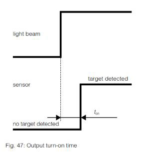
The output turn-off time toff is the minimum period of time required for a sensor to detect the absence of a light beam and output an OFF signal.
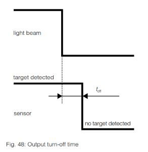
ton and toff are measured in accordance with IEC60947-5-2 2007 paragraph 8.5.3.
VIBRATION RESISTANCE
The sensors in this catalog are tested for resistance to vibrations of 1 mm amplitude at 55 Hz, according to IEC 60068-2-6.
VOLTAGE DROP
In the switched-through condition, a (current dependent) voltage drop develops across the output transistor; the output voltage, therefore, does not entirely reach the corre- sponding supply voltage (to be particularly taken into account with series connection and electronic inputs).
WIRE-BREAK PROTECTION
All sensors in this catalog are equipped with wire-break protection. If a voltage supply lead breaks, the output is disabled, thus avoiding an error signal.
WIRING
Sensor cables must not be laid in parallel in the same cable runs as cables connected to inductive loads (i.e. protection sole- noids, magnetic rectifiers, motors, etc.), or which conduct currents from electronic motor drives. Leads should be kept as short as possible; however, with suitable wiring (low coupling capacitance, small interference voltages), they can be up to 300 m long.
To reduce electromagnetic interference, apply the following measures:
? Maintain the distance to interfering cables > 100 mm
? Use shields
? Install inductances (contactors, mag- netic rectifiers, relays) with RC networks or varistors
12th Dec 2022