How To Install Sentrol Integrity Series INT-22-5R1-24
Edwards Signaling 12th Dec 2022
How To Install Integrity Series INT-22-5R1-24
Safety Instructions
Only trained professional electricians may install, startup, modify, and retrofit this equipment! Disconnect the device / system from all power sources prior to starting any work! If installation or system errors occur, line voltage may be present at the control circuit in devices without DC isolation! Observe all electrical safety regulations issued by the appropriate technical authorities or the trade association. The safety function can be lost if the device is not used for the intended purpose. Opening the housing or any other manipulation will void the warranty.
Caution!
Perform the following precautionary steps prior to installation, assembly, or disassembly:
1. Disconnect supply voltage to the equipment / system prior to starting any work!
2. Lockout/tag the equipment / system to prevent accidental activation!
3. Confirm that no voltage is present!
4. Ground the phases and short to ground!
5. Protect against adjacent live components using guards and barriers!
6. The devices must be installed in a cabinet with a protection class of at least IP 54.
Caution!
Limited contact protection! Protection type according to DIN EN 60529.
Housing/terminals: IP 40/ IP 20.
Finger-proof acc. to VDE 0660 Part 514.
Housing/terminals: IP 40/ IP 20.
Finger-proof acc. to VDE 0660 Part 514.
Base Device for Emergency Stop and Safety Gate
Applications
• Basic device to EN 60204-1 and EN 954 - 1
• Safety category 4 to EN954-1
• Stop category 0 to EN 60204-1
• Manual or automatic start
• Cross monitoring
• Feedback circuit for monitoring external contactors
• 3 enabling current paths
• Equivalent and non-equivalent activation
• Safety category 4 to EN954-1
• Stop category 0 to EN 60204-1
• Manual or automatic start
• Cross monitoring
• Feedback circuit for monitoring external contactors
• 3 enabling current paths
• Equivalent and non-equivalent activation
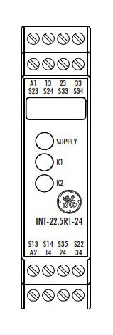
Front View
SUPPLY LED green Power Supply
K1 LED green Relay K1
K2 LED green Relay K2
K1 LED green Relay K1
K2 LED green Relay K2
Description of Device and Function
This device is a two-channel Interlogix safety switching device with self-monitoring on each ON-OFF cycle. It conforms to EN 60204-1 and is equipped with positively driven relays. It is intended for monitoring connected switching elements on separating safety devices and generating a safety- oriented output signal (enable). Depending on the design, separating safety devices may include protective screens, safety doors, enclosures, covers, screens, etc.
Basic function: After supply voltage has been connected to terminals A1/A2 and the safety inputs closed, operating the reset button closes the enabling current paths (manual start). When the safety inputs are opened the enabling current paths will open.
Operating modes / system functions
• Two-channel activation The device uses two-channel activation. With equivalent activation safety channel CH1 is connected via positive potential, safety channel CH2 via negative potential. With non-equivalent activation both safety channels are connected to positive potential.
• Cross monitoring With equivalent activation cross monitoring is achieved by means of the short-circuit principle; with non-equivalent activation it is achieved through functional diversity.
• Manual start When the safety inputs are closed, a button is used to close reset input S34 and then open it again (triggering with falling edge) or to close reset input S35 (triggering with rising edge).
• Automatic start Reset input S35 is connected to S33/S14. The device starts with the rising edge of the signal on safety input S14.
• Starting lockout After supply voltage has been connected and the safety inputs closed, the enabling paths will not close. Starting is only possible after the reset button has been operated. For starting lockout the reset inputs have to be activated with the button, as in manual start mode.
• Restarting lockout No restart after the safety inputs have been opened and closed. Restarting is only possible after the reset button has been operated. For restarting lockout the reset inputs have to be activated with the button, as in manual start mode.
• Synchro-check Synchro-check is only possible in automatic start mode (bridge S33/S14 - S35). After safety channel CH1, safety channel CH2 must close (S24) or open (S22) within the synchronous time tS. If CH2 closes or opens before CH1, the synchronous time tS = ∞.
Please observe instructions from safety authorities.
Proper Use
The devices are Sentrol safety switching devices. They must only be used as components of safety equipment on machines intended to protect persons, material and plant.
Notes
• The safety category acc. to EN 954-1 depends on the external circuitry, the choice of control devices and their location on the machine.
• The indicated times must be observed when the device is operated, otherwise the device could lock. Locking can be cancelled by opening the safety inputs properly.
• SNE expansion devices or external contactors with positively driven contacts can be used to duplicate the enabling current paths.
• The device and the contacts must be protected at max. 6 A utilization category gG.
• The devices are equipped with overload protection (for short-circuit). After the malfunction has been dealt with, the device is operational again in approx. 3 s.
• Control output S13 is exclusively for connecting control devices as defined in the operating instructions and not for connecting external
consumers such as lamps, relays or contactors.

Technical data
Power circuitry
Rated voltage UN AC/DC 24 V, AC 115 - 120 V, AC 230 V Rated power DC 2.0 W
Rated power AC 2.6 W / 3.2 VA Residual ripple USS 2.4 V
Rated frequency 50 ... 60 Hz
Operating voltage range 0.85 ... 1.1 x UN
Protection for control circuit supply Short-circuit-proof (DC devices: PTC thermistor / AC devices: short-circuit-proof transformer)
Control circuit
Outputs S13, S23
Rated output voltage S13, S23 DC 22 V No-load voltage AC device < 40 V
Output current 100 mA Short-circuit-proof / current limiting Yes / No
Inputs S14/S33, S22, S24, S34, S35
Input voltage range (for external supply, only on DC devices) DC 17.4 V to DC 26.4 V Rated current / peak current S14/S33, S22, S24 40 mA / 100 mA
Rated current / peak current S34, S35 5 mA / 50 mA
Times
Permissible test pulse time tTP / test frequency ≤ 1000 µs / ≤ 10 s-1
Operate time tA1 S34 20 ms to 40 ms Operate time tA2 S35 200 ms to 600 ms Operate time tA3 100 ms to 400 ms Min. ON time tM S34, S35 > 80 ms Synchronous time tS CH1 before CH2 approx. 200 ms Recovery time tW ≥ 100 ms
Release time tR K1, K2 < 25 ms
Output circuit
Enabling paths
Contact equipment 3 NO contacts, positively driven
Rated switching voltage Un AC 230 V / DC 300 V Max. continuous current In per current path 6 A
Max. total current for all AC/DC 24 V 12 A
current paths AC 115 - 120 V, AC 230 V 8 A
Utilization category according to IEC 947 - 5 - 1
AC-15: Ue 230 V, Ie 4 A (360 h-1) DC-13: Ue 24 V, Ie 4 A (360 h-1)
AC-15: Ue 230 V, Ie 3 A (3600 h-1) DC-13: Ue 24 V, Ie 2,5 A (3600 h-1)
Mechanical service life 10x106 switching cycles
General data
Clearance/creepage distance between circuits EN 60947-1:12.99
Overvoltage category III Rated impulse withstand level 4 kV
Contamination level of device: inside / outside 2 / 3
Rated voltage 300 V Power-frequency test voltage 2 kV
Protection class to DIN VDE 0470 Part 1: housing / terminals IP 40 / IP 20
Ambient / storage temperature -25 ... +55 °C / -25 ... +75 °C Climatic application class H V G to DIN 40040: 04:87
Weight
DC device 0.21 kg
AC device 0.25 kg
Terminals and connection
Single-core or finely stranded 1 x 0.14 mm² to 2.5 mm² 2 x 0.14 mm² to 0.75 mm²
Stripping length max. 8 mm
Finely-stranded with wire-end ferrule to DIN 46228 1 x 0.25 mm² to 2.5 mm² 2 x 0.25 mm² to 0.5 mm²
Max. tightening torque 0.5 to 0.6 Nm
For UL and CSA applications
Conductor sizes AWG 18-16 use only Cu lines
Max. tightening torque 0.79 in-lbs
Installation
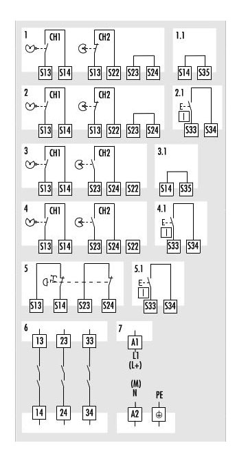
Please consult the connection diagram during installation.
Safety door (open) non-equivalent activation, automatic start, cross monitoring
Start
Bridge automatic start
Bridge automatic start
2.1 Reset
Safety door (open) non-equivalent activation, manual start, cross monitoring
Safety door (open) non-equivalent activation, manual start, cross monitoring
Reset button
(S14/S34 on AC device)
(S14/S34 on AC device)
Safety door (open) equivalent activation, automatic start, cross monitoring (S22 disconnected)
3.1 Start
Bridge automatic start
4
Bridge automatic start
4
Safety door (open)
equivalent activation,
Start,
manual start, cross moni-
equivalent activation,
Start,
manual start, cross moni-
4.1 Reset (S14/S34)
5.1 Reset-button
(S14/S34 on AC device)
(S14/S34 on AC device)
Emergency stop
two-channel, manual start, cross monitoring
two-channel, manual start, cross monitoring
Reset button
(S14/S34 on AC device)
(S14/S34 on AC device)
Enabling current paths
3 NO contacts, positively driven
3 NO contacts, positively driven
Supply voltage
PE on AC device only
PE on AC device only
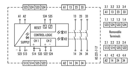
Connection Diagram
Montage, Assembly, Montage
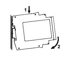
1 Attach relay to DIN rail.
2 Press the relay carefully onto the DIN rail (in direction of arrow) until it locks into place.
Disassembly
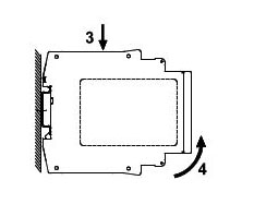
3 Push relay down (in direction of arrow)
4 Release relay and remove it from the DIN rail (see arrow)
Dimension Diagram / Dimensions
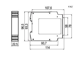
Subject to changes
Application Examples
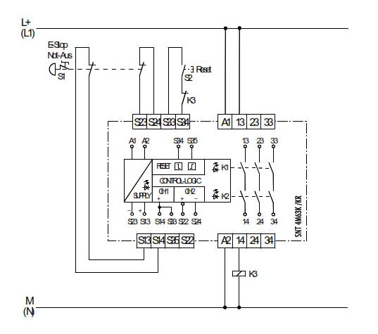
Dual channel Emergency Stop monitoring with two N.C. safety circuits, manual start, Reset-key monitoring and cross monitoring. In accordance up to safety category 4.
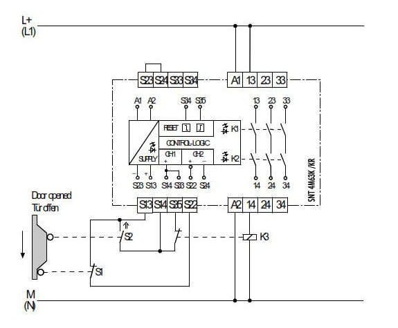
Dual channel GE Security safety gate switch monitoring with N.C./N.O. safety circuits, automatic start and cross monitoring.
In accordance up to safety category 4.
12th Dec 2022
