How To Install Sentrol Integrity Series INT-05 Safety Expansion Relay
Edwards Signaling 12th Dec 2022
How To Install Integrity Series INT-05 Safety Expansion Relay

Description
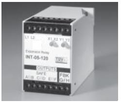
The Sentrol INT-05-024 or INT-05-120 Expansion Safety Relay is intended for use as part of a safety circuit. It provides three additional safe output contacts when used with the GE Security INT-03 Safety Monitor Relay or INT-04 Emergency-Stop Safety Relay.
The INT-05 uses positive-guided relays along with feedback contacts to the INT-03 or INT-04 safety relay to prevent machine start-up in the event of a component failure.
Voltage to the INT-05 is switched thru the contacts of the INT-03 or INT-04. If a component failure occurs, the feedback loop to the INT-03 or INT-04 prevents machine restart.
TUV Notes:
1. Relay conforms to Pollution Degree II, meets EN1760-1:1998, and must be installed in an IP54-type enclosure.
2. The wire insulation of connected devices must be rated for 250VAC. The relay meets basic insulation requirements only.
3. Input devices must meet requirements of EN60947-5-1.
4. The relay must be connected to a primary disconnect device that meets the requirements of EN60947-3.
5. Controller meets IP20.
6. Test system before operation and after machine maintenance. Controller does not require maintenance.
7. The complete system should be tested weekly. If a fault occurs, contact the factory.
8. To be used in conjunction with INT-03 or INT-04.
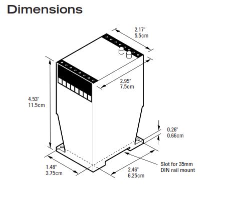
Dimensions

Installation
1. Mount the relay on a 35mm DIN rail or panel. See Dimensions.
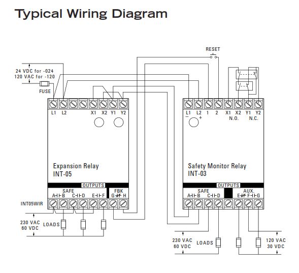
2. Connect the wiring for the Interlogix switches and relay. See Wiring Diagrams. (For proper operation, DO NOT jumper terminal 1 to terminal 2. Use a momentary button.) For floor mat applications, connect the two floor mat loops from terminal X1 to X2 and from Y1 to Y2.
Caution! The relay is available in either a 24 VDC, 120 VAC, or 230 VAC model. Make sure correct model is used before applying power.
3. Use one of the following methods to energize the relay:
• For E-stop installations, close all E-stop button contacts and monitored contacts, and then press the START button.
• For floor mat installations, press the START button without an object on the mat.
Note: The INT-05 must be wired as shown as the unit on its own does not fulfill any safety requirements.
Typical Wiring Diagram

European Directives
Machinery Directive (98/37/EEC)
Low Voltage Directive (73/23/EEC), LVD
Specific European Standards
EN60204-1 Safety of electrical equipment of industrial machines: 1993
EN954-1 Risk Assessment Category 4
depending on wiring method, See diagrams: 1997
EN50081-2 Electromagnetic Emissions: 1995
EN50082-2 Electromagnetic Immunity: 1995
IEC 664-1 Insulation requirements: 1992
IEC 68, part 2-1, 2-2, 2-3, 2-6, 2-14, 2-27, 2-30.
EN1760-1:1998
General Specifications
UL/CSA/TUV CSA submitted
Environmental Rating Pollution Degree II
Temperature Range 32°F to 149°F (-0°C to 65°C)
Relative Humidity 30 to 95% non-condensing
Control Inputs (X1, X2 & Y1, Y2 terminals)
Open-circuit voltage 24VDC
Closed-circuit current 24mA
Max. contact resistance 30 Ohms
Simultaneity 500 ms typical
Safe Outputs (A,B/C,D/E,F terminals)
Voltage 230 VAC/60VDC
Current 4A (resistive) each output
Response time ON: <40ms, OFF:<30ms
Fuse 4A, 250V, 5 x 20 mm
AUX. Signaling Outputs (F1,F2 terminals)
Voltage 120 VAC/30VDC
Current 1A (resistive)
Note: Transient protection is required across the load when switching an inductive load.
Ordering/Electrical Specifications
| PART NUMBER | POWER INPUT (L1, L2) | INPUT FUSE REQUIRED |
|---|---|---|
| INT-05-0241 | 24VDC +/-15% | Fast acting 1/4A (250V, 5 x 20mm, F) |
| INT-05-1202 | 120VAC +10% -20%, 5VA, 50/60Hz | Fast acting 80mA (250V, 5 x 20mm, F) |
1 Max of 80 expansion relays in series with INT-03 or INT-04.
2 Max of 1 expansion relay in series with INT-03 or INT-04.
2 Max of 1 expansion relay in series with INT-03 or INT-04.
12th Dec 2022


