How To Install Sentrol Integrity Series INT-04 Emergency-Stop Safety Relay
Edwards Signaling 12th Dec 2022
How To Install Integrity Series INT-04 Emergency-Stop Safety Relay

Description
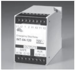
The Sentrol INT-04 Series Emergency-Stop (E-Stop) Safety Relays are designed for use as part of a safety circuit in emergency-stop or safety floor mat sensing applications. Each is a safety relay that uses positive-guided relays, configured for self-checking, to inhibit machine restart in case of internal component failure.
The GE Security INT-04 relay can also monitor contacts on external relays for controlling primary machine control elements or expansion block relays (INT-05 or INT-06).
TUV Notes:
1. Relay conforms to Pollution Degree II, meets EN1760-1:1998, and must be installed in an IP54-type enclosure.
2. The wire insulation of connected devices must be rated for 250VAC. The relay meets basic insulation requirements only.
3. Input devices must meet requirements of EN60947-5-1.
4. The relay must be connected to a primary disconnect device that meets the requirements of EN60947-3.
5. System total response time must not exceed 200ms.
6. Controller meets IP20 and must be connected to safety category 4 mat or sensing device.
7. Test system before operation and after machine maintenance. Controller does not require maintenance.
8. The complete system should be tested weekly. If a fault occurs, contact the factory.
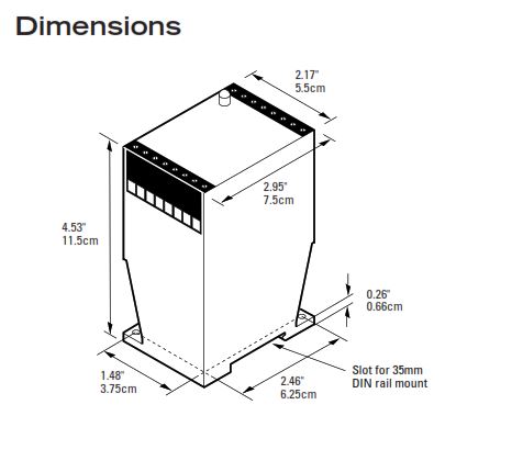
Dimensions

Installation
1. Mount the relay on a 35mm DIN rail or panel. See Dimensions.
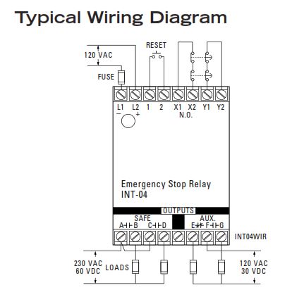
2. Connect the wiring for the switches and relay. See Wiring Diagrams. (For proper operation, DO NOT jumper terminal 1 to terminal 2. Use a momentary button.) For floor mat applications, connect the two floor mat loops from terminal X1 to X2 and from Y1 to Y2.
Caution! The Interlogix relay is available in either a 24 VDC, 120 VAC, or 230 VAC model. Make sure you are using the correct model before you apply power.
3. Use one of the following methods to energize the relay:
• For E-stop installations, close all E-stop button contacts and monitored contacts, and then press the START button.
• For floor mat installations, press the START button without an object on the mat.
Note: Use only outputs A, B, C, and D for safety outputs. The auxiliary outputs E, F, and G may fail in an unsafe condition and should only be used for signaling.
E-Stop Relay
When installed as an E-stop relay, the device monitors both contacts on the E-stop buttons to ensure both have opened and closed to allow machine restart. Multiple contacts can be wired in series. Upon failure of either contact, the relay turns off and prevents a restart.
Safety Floor Mat Relay
When installed as a Safety Floor Mat relay, the INT-04 monitors both loops of a safety floor mat. The safety outputs of the INT-04 turn off when an operator steps on the mat. The relay incorporates loop break detection to turn off if one of the loops breaks or becomes disconnected.
Typical Wiring Diagram

Auxillary Contacts
| Power | Reset (1,2) | E-Stops | E, F | F, G |
|---|---|---|---|---|
| Off | Open or Closed | Open or Closed | Closed | Open |
| On | Open | Open or Closed | Closed | Open |
| On | Open or Closed | Open | Closed | Open |
| On | Closed | Closed | Open | Closed |
European Directives
Machinery Directive (98/37/EEC)
Low Voltage Directive (73/23/EEC), LVD
Specific European Standards
EN60204-1 Safety of electrical equipment of industrial machines: 1993
EN954-1 Risk Assessment Category 4
depending on wiring method, See diagrams: 1997
EN50081-2 Electromagnetic Emissions: 1995
EN50082-2 Electromagnetic Immunity: 1995
IEC 664-1 Insulation requirements: 1992
IEC 68, part 2-1, 2-2, 2-3, 2-6, 2-14, 2-27, 2-30.
EN1760-1:1998
General Specifications
(TABLE-2-type-out)
Ordering/Electrical Specifications
| PART NUMBER | POWER INPUT | INPUT FUSE REQUIRED |
|---|---|---|
| INT-04-024 | 24VDC +/-15%, 100mA | Fast acting 1/4mA (250V, 5 x 20mm, F/T) |
| INT-04-120 | 120VAC +10% -20%, 5VA, 50/60Hz | Fast acting 80mA (250V, 5 x 20mm, F/T) |
12th Dec 2022


