The Sticking Reed Switch Problem
Edwards Signaling 12th Dec 2022
Protecting Against Voltage Spikes
The Sticking Reed Switch Problem
When Interlogix magnetic reed switches are wired in line with relay devices with coils, the reverse voltage spike generated when current is removed from the relay can fuse the switch contacts together.
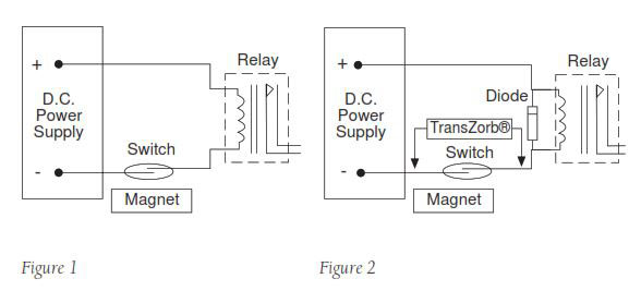
Figure 1 shows that when the contact is closed, current flows through the relay coil and magnetizes the iron core. When the contact is opened, current from the power supply stops and the magnetism of the relay iron drops to zero instantly. The collapsing magnetic field draws voltage into the relay coil. Since the coil is open (open reed switch) and there is no circuit loading to limit the voltage, spikes from the open relay can reach 500 volts or more, causing arcing across the reed contacts. (Most of Sentrol’s reeds arc between 150 and 200 volts, well within this reverse voltage kick.)
Repeated arcing roughens and pits the reed switch blades until they eventually stick together mechanically. Installers often find that tapping on the switch will cause the contacts to release (open). The "fix" is only temporary, however.
Correcting the Problem for DC Circuits
Voltage kicks or transients from DC circuits are easily controlled by adding a diode across the relay coil, as in Figure 2. The diode has no affect on the circuit when the current flows in the right direction. However, when current from the power supply stops suddenly and the relay coil generates a reverse voltage, it shorts through the diode. Note that the stripe on the diode points toward the + voltage. The diode used should be a #1N4002, 1N4003, 1N4004 or equivalent.
... and for AC Circuits
In AC circuits, current flows through the relay coil in both directions. Using a diode would simply short out half of every cycle. However, a transient protection diode, called a TransZorb, can be used to clip off voltage spikes in either direction as shown in Figure 2. TransZorb must be selected to fit the voltage used in the circuit. To find the correct TransZorb voltage rating, multiply the circuit voltage times 1.414. For example, in a 24 volt circuit a TransZorb rated at 34 volts or more may be used (24 x 1.414 = 34).
12th Dec 2022
