Determining Response Speed
 The response speed of SUNX sensor is an important feature that one should consider when specifying a sensor for an application, especially if that application involves high speed movement like many of today's manufacturing processes. However, it's very easy to overestimate what you really need based a perceived notion that a process is "ultra-fast". The high speed sensors that are available today are typically 1-2 orders of magnitude faster than most applications need, so understanding your requirements is the easiest way to maximize the performance, and decrease the cost, of your sensor solution.
What is Response Speed?
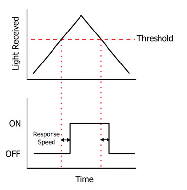
Response speed is the length of time that a sensor needs to react and activate its output after it senses a breach of the threshold value that has been set.

In the diagram above, as the light received moves above the threshold value, there is a slight delay in time before the sensor's output turns on. This is the response speed of the sensor. You'll also notice, however, that the same response time exists when the output turns off. This becomes very important when counting parts in high speed, because you must also consider the sensor's ability to reset the output and become ready for the next part to pass by.
How fast of a sensor do I need?
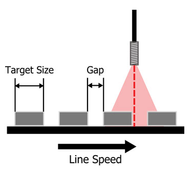
Now that we understand that the response time of a sensor applies to both ON and OFF conditions, we can now evaluate our needs based on our application specifics. In a typical counting application, as shown below, your response time requirements will depend on three variables, the size of the part to be detected, the gap between parts, and the speed that the manufacturing line is moving.
You will notice in our example that the gap is much smaller then the part itself. In this case, we must use this distance in determining our needed response, because it is the shorter of the two dimensions. If we were to use the target size in our calculations, we may find that the sensor has the speed to turn on; however that may not be the case when turning off, so we would run the risk of having the sensor turn on once and not turn off at all.

To evaluate our response time requirement you will need to determine the length of time that a condition will be presented in front of the sensor. The red, dashed line in the figure above signifies the point at which the threshold of our sensor will be breached. In the case of a fiber optic sensor, the repeatability of this point can be a small as 10 microns, provided that the part to part variance is small. This allows us to simplify our calculation to the following equation:

In our example, the detection size is equal to the gap between parts. Let's say that the gap is ¼ inch and the line speed is 400 inches / sec. The response speed would need to be at most 0.625 ms in order for the output to properly reset. Therefore, SUNX Ltd. FX-301 fiber amplifier would be usable in every mode except for long range mode, which has a response speed of 2ms. Standard mode, at 0.25 ms, would be 2.5X faster then the needed response speed for this application to work. As the part size gets smaller, and the line speed increases, the response speed needed will be proportionately faster. To put this into perspective, in order for you to reach the limit of our fastest sensor, FX-301-HS, that has a response speed of 35 microseconds, you would need a part that is 1/8" traveling at a speed of around 300 feet per second! This is far greater then anything that the fastest manufacturing line today can produce.


