Understanding SSI Encoders
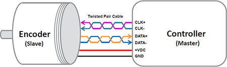
 Synchronous Serial Interface, or SSI, is a simple serial communications protocol designed for data transfer between computers or user terminals and smart sensors. Model MA and SA series absolute encoders from Encoder Products Company are always slave devices. The fieldbus device is the master, supplying a clock signal to which the encoder responds synchronously.
Understanding SSI Encoders
The SSI Master must be configured to the correct data word length and clock rate.
The master must also be configured to display the correct data type (Gray or binary code) supplied by the encoder.
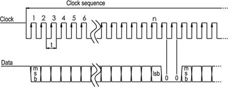
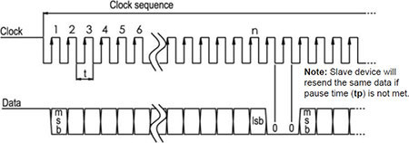
The SSI Master controls the data flow from the encoder data output by sending clock sequences to the encoder clock inputs.
The encoder electronics respond to the first falling slope of the clock sequence by freezing the current position value and starting the serial output of the data bits.
On every following rising clock edge from the master, one data bit is transmitted by the encoder.
After the last falling edge of the clock, the encoder pulls the dataline low for a period of time called the pause time (tp). After tp, the encoder will pull the dataline back to its high idle state and will load its updated position data. During this time, the master must wait for at least 30µs (tm) to begin sending more clock signals. If clock signals are sent prematurely, the encoder will resend the previous data, and will not send updated data until the pause time (tp) has been met.
Single SSI Data Transmission:
This is called multi-path transmission. Multi-path transmission can be used to check data integrity by reading the data twice and verifying the data matches. However, the encoder will continue to send the same position data until the pause time (tp) has been met.
Multi-Path SSI Data Transmission:
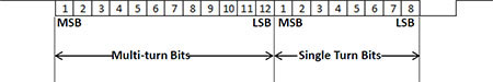
The encoder data bits are sent MSB to LSB, with multi-turn position bits sent first (if applicable), followed by single-turn position bits.
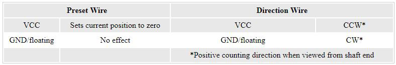
The MA and SA Series absolute encoders have two additional functions: preset and direction.
Multi-turn Data Format:
The preset wire defines the current actual shaft position as zero position if it is set to the supply voltage level for more than two seconds.
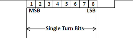
Single Turn Data Format:
The direction wire defines the positive direction of counting when the shaft rotates.
The standard direction is defined as positive counting during CW rotation when viewed from the shaft end. In this case, the direction is connected to GND. By connecting the direction wire to the supply voltage, the direction of counting changes to CCW. Changing the counting direction requires a reset of the encoder and may require an additional preset.
Maximum Data Transmission Rate
The data transmission rate is dictated by the master clock frequency. The maximum transmission rate is dependent upon cable length.

Noise Protection
Noise protection is extremely important for proper encoder operation, especially when data is being sent serially.
The following tips will help increase noise protection:
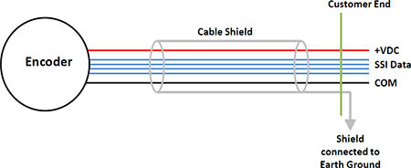
- Using shielded twisted pair cable is HIGHLY recommended.
- It is extremely important that cable shields are connected to the receiver/instrument (counter, PLC, etc.) • ground. When doing so, do NOT connect the end near the encoder. Connecting the shield at both ends can cause ground loops.
- Always make sure the motor/machine for which the encoder is mounted is properly grounded.
- The encoder case should also be grounded with the following conditions:
- DO NOT ground the encoder case through both the motor/machine and the cable wiring
- DO NOT allow the encoder cable wiring to ground the motor/machine exclusively. High motor/machine ground currents could flow through the encoder wiring, potentially damaging the encoder and associated equipment.
- Connecting cables should be kept away from power lines and other noise-generating equipment.
- Interference sources including motors, solenoid valves, and frequency converters should always have their noise suppressed at the source.
- Encoders should not be powered from the same main supply as solenoid valves or contactors, as this could likely cause interference.
- It may be necessary to install additional noise protection in certain applications.
