Tips for Mounting Inductive Proximity Switches
Contrinex 12th Dec 2022
Why inductive?
Inductive proximity switches are highly popular with end-users. They are
- robust
- good value for money
- insensitive to dirt
- standardized
- good value for money
- insensitive to dirt
- standardized
and, as a result, simple to employ.
1. Type of mounting embeddable/non-embeddable
In his documentation, the manufacturer indicates whether a particular device is intended for embeddable or non-embeddable mounting. This information relates to the permissible location of the device's sensing face in relation to the mounting surface, and is only of concern where there are metal surroundings. Insulating parts do not influence the functioning of inductive proximity switches. Metal parts in the vicinity of the sensing face on the other hand, influence the operating distance, though in various ways:
- Ferromagnetic metals (iron, nickel, cobalt, etc) increase the operating distance;
- Non-ferromagnetic, but good conducting metals (aluminum, brass, copper, etc.) reduce the operating distance;
- Non-ferromagnetic, poor conducting metals (stainless steels, zinc, etc.) can, according to the situation, increase or decrease the operating distance to a greater or lesser extent. The actual behavior must be determined from case to case.
As a matter of principle, mounting should not alter the operating distance by more than 10%. As a rule, the manufacturer's indication concerning embeddable I non-embeddable mounting also refers to this value. Some information concerning various mounting situations is given below:
1.1. Embeddable mounting (Fig. 1)
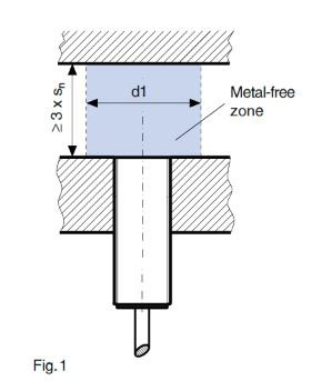
The sensing face of the proximity switch can be located in the same plane as the metallic mounting surface (naturally, it may also protrude if so desired). The mounting surface is allowed to fit tightly around the device; it may for instance also have a tapped fixing thread. Technically, this feature is made possible due to the fact that the field emitted from the device is formed by appropriate tailoring of the magnetic field and shielding into a hemisphere, which does not, or only minimally at least, extend beyond the outside diameter of the device. As a result, the achievable operating distance is consequently reduced. However, in addition to the possibility of embeddable mounting, the user obtains a better defined, well-limited profile of the sensitive area compared to other designs. These devices can be recognized by the fact that the plastic cap of the sensing face does not protrude beyond the metal housing. Consequently, the sensing face is better protected against mechanical damage. Considering these advantages, embeddable mounting devices should therefore be chosen wherever possible.
1.2. Recessed mounting (Fig. 2)
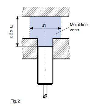
No proximity switch specified as "embeddable mounting" should just be simply mounted in a recessed position. When this method of mounting is envisaged, additional clarification is essential. It is generally valid that small sizes rather than large ones may be recess mounted. In any case, it is recommendable to take a measurement, so as to ensure that the operating distance is not altered by more than 10% when mounted. In case of doubt, it is worthwhile questioning the manufacturer, enclosing a mounting sketch.
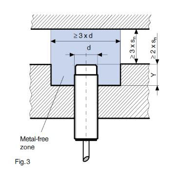
1.3. Non-embeddable mounting (Fig. 3)
The sensing face of the proximity switch must protrude significantly beyond the metallic mounting surfaces, namely by the value X (it can naturally protrude more if required). Further, with off-set mounting, value Y has to be taken into account. X and Y are generally indicated in the manufacturer's documentation; failing this, the values given in the standard (IEC 60947-5-2 or EN 60947-5-2I) may be consulted. These devices can be recognized by the fact that they have a protruding plastic cap. In comparison to embeddable executions, their operating distance is greater. However, the mechanical protection is, in all cases, worse, and the sensitive zone extends significantly beyond the diameter of the device. In general, there is no difference in price.
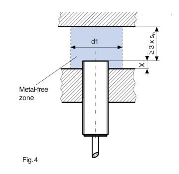
1.4. Quasi-embeddable mounting (Fig. 4) The sensing face of the proximity switch must protrude only insignificantly beyond the metallic mounting surfaces, namely by the value X (it can naturally protrude more, if required). In addition, a gap d1 must be maintained. X and d1 should always be given in the manufacturer's information. As in the case of fully embeddable types, these devices are recognizable by the fact that the plastic cap of the sensing face does not protrude beyond the metal housing, and are therefore better protected against mechanical damage.
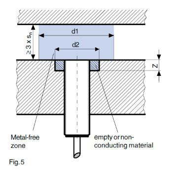
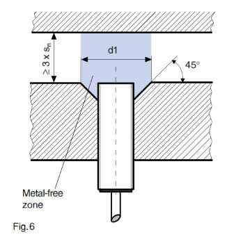
Inasmuch as protrusion of the proximity switch beyond the mounting surface is undesirable, off-set mounting according to Fig.5 can be used. In this case, the off-set mounting distance Z and the mounting diameter d2 must be taken into consideration, and these may exceed but never fall below the given values. In general, these measurements should be obtained from the manufacturer. According to the application, with a further variation (Fig.6), a more economical machining of the support can possibly be achieved.
2. Surrounding metal parts
Not only metal parts in the plane of the sensing face, but also those alongside or in front, influence the field and consequently the response of the device. As far as the type of metal is concerned, the information given in section 1 is also valid in this case. As a result of the vast number of mounting possibilities, useful information from the manufacturer is limited. When the spaces referred to in Figs.1 to 6 as "metal-free zones" can really be kept free of metal, then problem-free operation can be assumed. In principle, in this case, the following is also valid: as a result of embedding conditions, the operating distance should not vary by more than 10% relative to its value in free surroundings. If there is any doubt, this must be checked by means of a measurement.
3. Operating distance adjustment
The rated operating distance of a device can be obtained from the manufacturer's documentation, and is measured according to the relevant standard (EN 60947-5-2). In practice however, the actual operating distance is unfortunately dependent on numerous influences, the most important of which are described below:
3.1. Manufacturing scatter
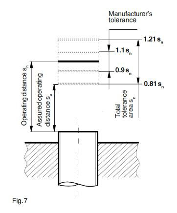
The standard allows the manufacturer a rated operating distance scatter of ±10%, which must be taken into account in the design (Fig. 7).
3.2. Influence of temperature and voltage
The standard requires that within the indicated temperature range (normally -25 T +70°C) and supply voltage, the operating distance does not vary by more than
10% of the value at 23°C and nominal supply voltage. Under factory conditions (+15 T +30°C), a temperature influence of s ±2% can be assumed.
3.3. Geometrical influence
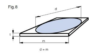
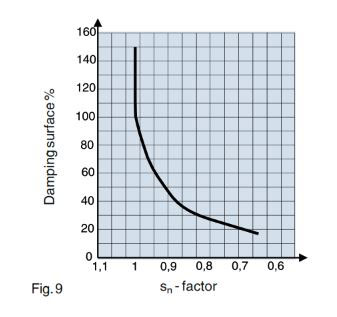
The given rated operating distance relates to the standard target defined in the above-mentioned standard. This target is made of steel, e.g. type FE 360 according to ISO 630, having a smooth surface, a square shape, and a thickness of 1mm (Fig.8). The side of the square is equal to the diameter of the inscribed circle of the sensing face or to three times the rated operating distance sn of the proximity switch, whichever is the greater. Larger measuring plates result in only slightly higher operating distances. On the other hand, other real operating distances, unfortunately in practice nearly always smaller, arise as a result of different objects (smaller surface, elongated shape, bending, surface condition), as a result of device-typical field flows. Only with foils can the attainable operating distances be greater. The following graph shows the geometrical influence for flat objects:
3.4. Material influence
The specified rated operating distance refers to steel objects, according to ISO 630. For other metals, this value must be adjusted using a correction factor. Below are given a few typical correction factors:
- Brass sn x 0.50
- Aluminum sn x 0.45
- Copper sn x 0.40
- Nickel-Chrome sn x 0.90
- Stainless steel V2A sn x 0.85
These correction factors are only indicative; the actual values must be taken from case to case from the technical information, or determined. They are dependant on the size of the device, whether mounted embeddable or non-embeddable, the exact alloy, etc. For some time moreover, there have been devices in the market that boast a correction factor of 1 for all metals.
3.5. Aging
With inductive proximity switches, aging effects, except when used under extreme service conditions, are negligible.
Practical rule
The following procedure has proven itself in practice:
- Mount the device in the designated position.
- By moving the device or the object, ascertain the effective operating distance.
- Position the proximity switch at 0.9 times the measured effective operating distance and secure it.
- By moving the device or the object, ascertain the effective operating distance.
- Position the proximity switch at 0.9 times the measured effective operating distance and secure it.
By this means, the assured operating distance in the actual application is reliably maintained.
4. Mutual influence with aligned devices
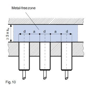
The mounting of several proximity switches with limited spacing (Fig. 10) can, as a result of inductive coupling between the oscillator coils, lead to mutual influence and as a result, to signal fallout. This case deserves particularly careful clarification, since the disturbances are not always immediately conspicuous, but may only occur sporadically. For such installations, the corresponding information from the manufacturer concerning the minimum spacing to be observed should first be consulted, and whenever possible adhered to. If in a specific case it cannot be adhered to, there are various possibilities:
- Install embeddable devices, since the required spacing compared to the housing diameter is significantly smaller;
- Use smaller proximity switches; the required spacing is disproportionately smaller;
- As far as the application permits, switch the supply voltage to the device on and off in such a way that neighboring units are never under tension at the same time. For instance, with processes that are not too fast, a kind of multiplex operation that removes disturbances in an elegant manner can be arranged;
- Use devices with different oscillator frequencies. These are available from most manufacturers as special versions. Two frequencies are often enough, provided the devices with these frequencies are installed alternately. This solution is however problematic for several reasons:
- special devices, which are more expensive and not stock items, are required;
- the risk of mix-ups during mounting is considerable;
- the logistical cost (spare parts stock, additional article, stock lists) increases;
- problems during the field replacement of spare parts can hardly be avoided.
- Use devices with the same dimensions, but from different suppliers. In this case, the oscillating frequencies are generally different, but this must first be clarified. Since oscillator frequencies are not given in catalogs, they must be requested from the manufacturer. The frequency difference should be at least 10%. For mounting, the information given further above is valid.
It is strongly advised to avoid any action just on the off chance that it may work. The oscillator frequency scatter between devices of the same type and the same manufacturer can often be enough to achieve a seemingly good result without further measures. Though whether next time it still works is a question of pure luck, to say nothing of mounting spare parts in the field.
5. Fixing
5.1. Threaded cylindrical devices
In compliance with the manufacturer's instructions, the maximum tightening torque of the nuts must be respected; the housing is hollow inside and therefore supports less load than a screw with the same diameter (Fig. 11). This is particularly important for small sizes. Moreover, it must be borne in mind that the wall thickness of the housing can be thinner for a few millimeters at each end, and that therefore the given tightening torque may perhaps not be attainable at these points. Where vibrations are present, the use of an additional safety-locking washer is recommended.
Tightening torque (Fig. 11)
- M8 x 1 2.5 Nm
- M12 x 1 10 Nm
- M18 x 1 20 Nm
- M30 x 1.5 40 Nm
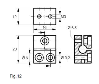
5.2. Smooth cylindrical devices
Smooth-walled devices are best fixed by means of clamps (Fig. 12). Cementing may also be possible. The use of adjusting screws should be avoided; they lead to deformation of the housing, and can lead to total device failure.
5.3. Square devices
It must be ensured that the mounting surface is sufficiently smooth, so that when tightening the fixing screws, the device is deformed to a negligible extent only. In this case also, where vibrations are present, the use of an additional safety-locking washer is recommended.
6. Connector / Cable Assemblies
In a number of cases, particular attention should be paid to the choice of connecting cable:
6.1. Use in oily environments
PVC-based cable insulation in permanent contact with any kind of oil will become brittle in time. This must also be avoided in static installations, since bending, e.g. during maintenance work can never be completely excluded. Cables with PUR insulation offer a good alternative in such cases. However, it is perfectly sufficient for only the sleeve coat to be of this material.
6.2. Use in chemically aggressive environments
The suitability of insulating materials such as PVC and PUR must be clarified from case to case since, according to the chemicals in question, there can be large differences in resistance. It is advisable to consult the plastic manufacturer's resistance tables. When absolute security is required, Teflon insulation is without equal. However, a few disadvantages must be accepted:
- Special execution of the proximity switches with the corresponding effects on logistics;
- Significantly higher price;
- Difficult processing.
6.3. Use with periodical flex-bending of the cable
For this type of stress, elementary construction rules must be considered:
- Keep the bending radius as large as possible;
- Avoid sharp bends at edges, especially at the cable exit from the proximity switch housing (Fig. 13). The use of fixing straps may be considered;
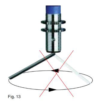
- Avoid self-vibration of the cable loops, or provide damping;
- Install grommets to protect against bending.
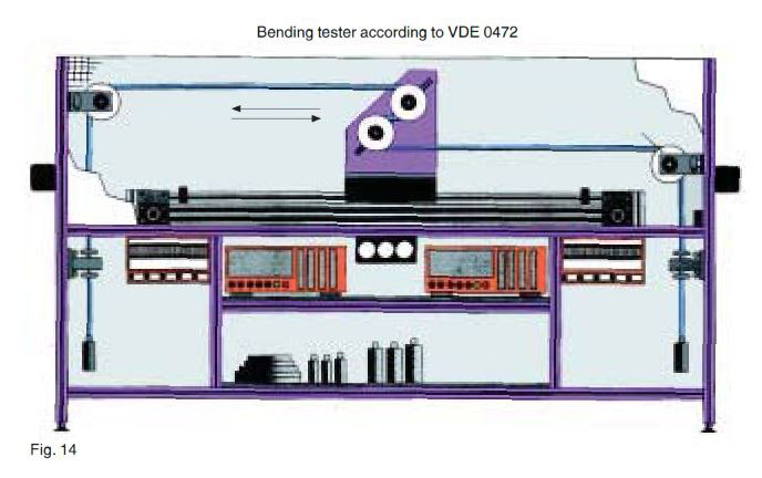
As a further measure, the use of cables with improved flex-bending strength is recommended, e.g. according to DIN VDE 0472, part 603, test method HIF (Fig. 14), minimum 20,000 cycles. Fine wire flex does not always give the best flex-bending strength. The flex-bending strength is rarely indicated in the manufacturer's documentation; in this case, inquire direct.
6.4. Use in low temperature environments
Normal PVC insulation becomes stiff at a temperature of 0°C, and brittle below -25°C. This is no problem for static mounting, since maintenance work is not normally carried out at these temperatures. If static mounting cannot be guaranteed, cables with PUR insulation offer a suitable alternative down to -40°C. For lower temperatures, silicone rubber insulation is without equal.
7. LED
If possible, the LED should be visible after mounting, for which the commissioning and maintenance personnel will be thankful. It is often sufficient to turn the device in the right direction. For devices with cable connections, a rear oriented LED is advantageous for visibility; on the other hand, this is often a disadvantage for the quality and durability of the seal between the housing and cable. For devices with socket connections, the use of a connecting lead with a built-in LED can guarantee a better visibility.
8. Labeling
In the case of spare part mounting, the importance of the device label should not be underestimated. For this reason, it is not of primary importance to place a high value on an aesthetically satisfactory label, but rather more on a permanent one. This is especially valid in a mounting situation where the device is in permanent contact with liquids. Less recommendable is the application of the label on the sensing face.
As is well known, despite all precautions, abrasion (which in addition also endangers the life of the device) must be reckoned with. It must be borne in mind that, in case of failure, the label may no longer be readable.
The manufacturer's original labeling is nearly always carefully optimized, and therefore of good quality. The problem frequently only arises when the user applies company-specific additional labeling, e.g. part numbers. The additional cost required to provide first-class durability is easily dispensed with and, as a result, problems when replacement parts need installing are involuntarily provided.
12th Dec 2022
