New Pressure-Resistant Switches for Highly Dynamic Uses
Contrinex 12th Dec 2022
Pressure-resistant inductive proximity switches were developed for a multitude of uses: from all applications in the area of hydraulic technology to many uses within the domain of pressure (up to 500 bars). Pressure resistance of the switch is dependent on the thickness of the casing walls particularly in the region of the sensing face. Herein lies a problem: to guarantee an acceptable switching distance with these thicker walls.

Pressure Resistance
These new proximity switches are built exclusively in the 'direct way', with enough case strengthening for high pressure resistance up to and over 500 bars. A ceramic disk is used on the sensing face which has enough thickness to withstand the pressures without further reinforcement measures. There is also no need for any further auxiliary construction, for example, the use of internal supports. The entire electronic module, including the ferrite core and the coil, are installed as an internal component in the pressure free environment of the casing. However, as a result of the thickness of the ceramic disk 2.5 mm (P20), when the proximity switch module with a normal operating distance (in this example, 2 mm) is installed, the useful measuring distance is less than zero. The solutions to these problems are described below.
Fixing and sealing of the front face.
Pressure resistance, out of pure necessity, requires a seal of some sort so that at maximum operating pressures there is no infiltration of harmful mixtures of liquid or gas. Such a seal is particularly necessary between the 'squared up' side of the ceramic disk and the metallic casing.
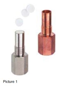
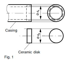
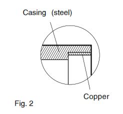
With new proximity switches, success has been achieved by shrinking the casing around the ceramic disk. Picture 1 shows the casing and the ceramic disk before and after assembly, and Fig. 1 shows the part in cross-section. Assembly is made by heating the casing in the joining area (which can be achieved, for example, in a few seconds using induction heating). While the casing is still hot, the ceramic disk is placed in position without using any mechanical force. The whole assembly is then left to slowly cool. The metal casing will shrink much more than the ceramic disk, due to the higher temperature coefficient of metal. With suitable choices, the dimensions dt and d2 will result in a powerful and tight seal. However, even with this, the joint is not satisfactorily tight. The gas impermeable sealing is achieved with the insertion of a thin layer of copper between the casing and the ceramic disk (see Fig. 2). For this, the entire casing is copper plated before shrinking, and then the copper plating is removed after shrinking. At the joint the copper is not removed, which brings about a connection which, with the shrinking process, produces a mechanical pressure of up to 200 N I mm2 on the surfaces, which produces a superior sealing.
Operating Distance
As described above, a large amount of useful operating distance is lost due to the thickness of the ceramic disk. All the same, a satisfactory operating distance is produced by installing an electronic module with a large operating distance (approx. 3 times Condist Oscillator) in place of a normal electronic module. The resulting operating distance for type P20 is 3 mm, which is even higher than a simple unit without a ceramic disk (2 mm).
Dynamic Requirements
Conventional pressure-resistant proximity switches are only conditionally suited to dynamic pressure uses. When used in the normal way the support system and the teflon seal will wear out after a certain number of pressure cycles. Experience of this comes through experience with practical applications, in particular with hydraulic systems. These new proximity sensors in this respect are completely different. With their simple installation in combination with the higher mechanical surface pressure of the casing on the ceramic disk, they are highly insensitive in dynamic situations and against pressure peaks.
Design
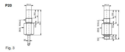
The following devices are available as described (Figs. 3 and 4).
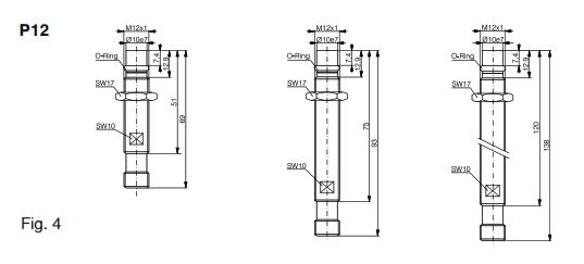
Costs
The devices make do with fewer and simpler mechanical parts. The installation is made in fewer steps and without any special skills. The electronic modules are the same as those already mass-produced for long-range switches. These devices are therefore, despite their advantageous properties, unusually economical in their manufacture.
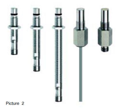
Advantages
- A practically unlimited number of pressure cycles permissible over the full pressure range
- Large operating distances
- Gas tight joining in the area of the sensing face
- Simple mounting. lnstall against a limiter: and finished! No adjustment is required (P20).
- Favourable cost
Applications
The new devices are available on the market as advantageous replacements - especially considering their easy attachment, their long operating distance and low price. Their application is however, especially reputable where dynamic pressure stress is expected, for example:
- lnterrogation of the piston end position in hydraulic cylinders;
- Control and monitoring of the switches of hydraulic valves;
- rpm counting and monitoring of hydraulic motors;
- Control and monitoring valve switching in gas distribution systems (the devices are gas impermeable);
- Applications within high-vacuum installations.
Technical Data:
(According to IEC 60947-5-2)
| P20 | P12 | |
|---|---|---|
| Max. operating pressure | 500 bars | 500 bars |
| Max. peak pressure | 800 bars | 800 bars |
| Operating distance | 3.0 mm | 1.5 mm |
| Hysteresis | 10 % typ. | 10 % typ. |
| Supply voltage range UB | 10 ... 30 VDC | 10 ... 30 VDC |
| Maximum ripple content | 20 % | 20 % |
| Output current | ≤ 200 mA | ≤ 200 mA |
| Output voltage drop | 2.0 V max. at 200 mA | 2.0 V max. at 200 mA |
| Switching frequency | 500 Hz | 2,000 Hz |
| Operatingtemp. range | -25 ... + 80 °C | -25 ... + 80 °C |
| Protection degree | ||
| at active face: | IP 68 | IP 68 |
| connection side: | IP 67 | IP 67 |
| Housing material | Stainless steel | Stainless steel |
| Sensing face | Ceramic Al2O3 | Ceramic Al2O3 |
| EMC protection: | ||
| IEC 60255-5 | 1 kV | 1 kV |
| IEC 61000-4-2 | Level 2 | Level 2 |
| IEC 61000-4-3 | Level 3 | Level 3 |
| IEC 61000-4-4 | Level 2 | Level 2 |
12th Dec 2022


