Diffuse Sensors with Cylindrical Detection Zone
Contrinex 12th Dec 2022
The problem
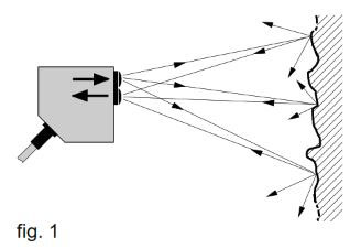
Diffuse sensors enjoy great popularity with users and are consequently often employed. With these devices, the pulsed light from the emitting diode falls on an object of any shape or color, from which it is reflected in a diffuse manner. In turn, part of this reflected light reaches the light-receiving device, which is located in the same device (fig.1). If the intensity of the received light is sufficient, the output is switched. Operating distances depend on target size, color and surface structure.
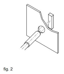
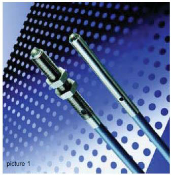
The use of diffuse sensors is generally trouble-free. However, an almost insoluble problem appears when devices with very small diameters, short operating distances and/or narrow total beam angle are called for. Very small diameter devices are to be understood as M5 or less. Below is an example:
Technical situation
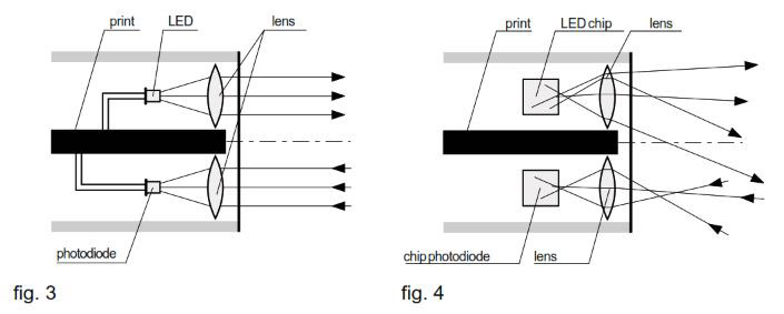
Conventional diffuse sensors work using optical lenses. It should be noted here that, in the same device, two optical systems are required, namely one each for the emitter and the receiver.
No appreciable problems arise when scaling down these optical systems where small devices have to be made. However, there are fundamental limitations. The lenses themselves can be reduced in size almost indefinitely, but the dimensions of the transmitter and receiver components cannot. Light emitting diodes (LEDs), which are available down to very small housing sizes, are generally used as the transmitters. Nevertheless, these housings are still much too large for really small reflex sensors.
Thus, the only solution remaining is a change to unhoused chips, whose use is, however, linked to considerable additional costs. Only now can the basic problem be recognized. By way of illustration, such an optical system is shown to scale in fig. 4. It can immediately be seen that the LED chip is extremely large in relation to the lens diameter. Inevitably, a very poor beam quality results. Both the quantity of output-coupled light and the total beam angle on the transmitter and receiver sides leave much to be desired. Smaller LED chips would, of course, be the solution, but these unfortunately do not exist. An additional disadvantage is that the roughly cubic LED chips emit their light more or less uniformly in all directions. On the receiver side, incidentally, the situation is no better.
An elegant and effective solution for light coupling and shaping has been realized by Contrinex in the form of its cylindrical miniature devices (series 1040 / 1050), in which the lenses have been replaced by concave mirrors.
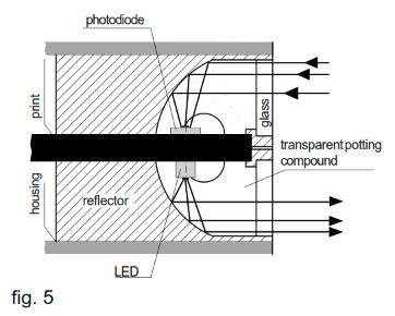
The result clearly is impressive, at least as far as the operating distance (50 mm) is concerned. The total beam angle of ± 22° is however quite large, in fact too large for many applications.
For light-based detection assignments on a miniature scale, optical fibers are very well suited. There is no need to enter into their numerous advantages here. However, all optical fiber solutions likewise suffer from the disadvantage of a large total beam angle, so that the problem mentioned above is still not resolved. The total beam angle of optical fibers is essentially given by the numerical aperture of the optical fiber material, and cannot therefore be influenced.
From a technical point of view, the obvious solution is to choose lasers where narrow total beam angles are required. However, laser devices today cannot even nearly be inserted into such small housings as users would wish. In addition, there are economic considerations that currently limit the more widespread use of laser devices.
New technique: Spherical optics
Principle of the technology
In view of many unresolved detection problems in the miniature field, Contrinex decided to look for new solutions. Not without success! Our work has shown that, surprisingly, amazing results can be achieved with spherical optics.
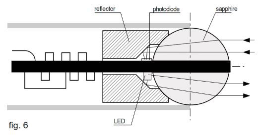
In order to separate the transmitter and receiver parts, a sapphire sphere is cut in two. Between the two halves of the sphere, there is an opaque layer to prevent an optical short-circuit. The transmitter and receiver semiconductor chips are mounted as closely as possible to the surface of the sphere. As can be seen in fig. 6, the chips (LED and photodiode) are somewhat off the optical axis. This is normally a disadvantage in optics, but not in this case, since the transmission beam and the detection zone of the receiver part “squint” somewhat, i.e. they cross at a certain distance from the device. As a result, the detection zone is approximately cylindrical. Understandably, this arrangement does not give optimum light efficiency. In this case, however, this can be easily accepted. The optical system described above is vacuum potted together with the electronics module in transparent resin.
Notes on performance
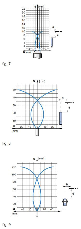
Fig. 7 shows the response curve of the new device (execution with 10 mm operating distance). For comparison, the response curves of previous Contrinex miniature devices (fig. 8) and a typical optical fiber (fig. 9) are also shown.
The remaining performance data is unchanged.
Technical data:
(according to IEC 60947-5-2)
Operating distance 10 / 20 mm
Supply voltage range UB 10 ... 30 VDC
Output current 100 mA
No-load supply current 15 mA
Switching frequency 250 Hz
Switching times 2.5 msec
Max. ambient light:
Halogen light 5,000 Lux
Sunlight 10,000 Lux
Ambient temperature 0 ... + 55 oC range
Degree of protection IP 67
EMC protection:
IEC 60255-5 1 kV
IEC 61000-4-2 Level 2
IEC 61000-4-3 Level 3
IEC 61000-4-4 Level 2
Products
Two groups of the new devices are presently available:
- one group with a 10 mm operating distance and narrowest total beam angle;
- a second group with a 20 mm operating distance and a somewhat wider total beam angle.
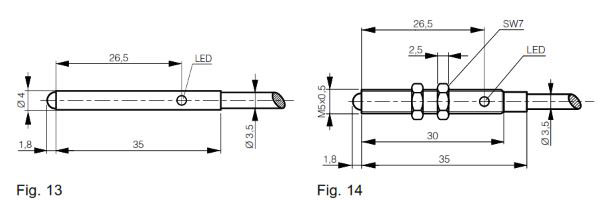
For both groups, there are cable executions in D4 and M5 housings, PNP and NPN switching. All the usual functions are built into the devices and, thanks to the stainless steel housings and vacuum potting, they are highly resistant to environmental influences. The electrical data corresponds to that of larger executions.
Application examples
Detection through holes and gaps
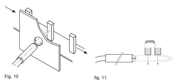
The detection of objects through holes and gaps is only possible in a very limited way with diffuse sensors currently available in the market. However, the new devices succeed in such applications, even in the case of small diameters or gap widths (fig. 10).
Operating-distance independent approach
With laterally approaching objects, whose distance from the switch cannot be kept constant, there used to be considerable variations in the switching point with previously known models. Here, the new devices yield much better results (fig. 11).
Longer operating distances than inductive devices
Inductive proximity switches are also available in the above-mentioned sizes and, strictly speaking, would be very suitable for solving the problems described above (as long as the objects to be detected were electrically conducting). However, their operating distances are very short (0.8 ... 1.5 mm) and, as a result, frequently insufficient. The closest alternatives are photoelectric devices. However, until now, the smallest operating distance with these was about 50 mm. For operating distances between 1.5 mm and 50 mm, nothing has been available until now. The new devices fill this gap.
Detection of closely lined-up objects
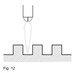
The wide beam of conventional photoelectric devices makes the detection of closely lined-up objects, gear wheels, grids etc. almost impossible. The new technology, on the other hand, gives very good results here (fig. 12).
Dimensional drawings
12th Dec 2022


